Powered device and power distribution system comprising the powered device

a technology of power distribution system and powered device, which is applied in the direction of power distribution line transmission, data switching details, instruments, etc., can solve the problem of increasing the power consumption of the powered device, and achieve the effect of increasing the power consumption

Active Publication Date: 2016-06-09
SIGNIFY HLDG BV
View PDF6 Cites 14 Cited by
  • Summary
  • Abstract
  • Description
  • Claims
  • Application Information

AI Technical Summary

Benefits of technology

[0008]Since the powered device comprises an electrical load power providing unit that generates the electrical load power with a power level such that the input current drawn by the powered device from the power sourcing device is maximized below a predefined upper input current threshold, the electrical load power and, thus, the power consumption of the powered device can be maximized within the limits resulting from the upper input current threshold. This allows for an increase of the power consumption of the powered device.
[0021]generating from a power sourced by a power sourcing device of the system to the powered device an electrical load power and providing the electrical load power to the electrical load, by an electrical load power providing unit of the powered device, wherein the electrical load power is generated by the electrical load power providing unit with a power level such that an input current drawn by the powered device from the power sourcing device is maximized below a predefined upper input current threshold, allowing the powered device to consume more power than allowed to the powered device according to a negotiated power class.

Problems solved by technology

This allows for an increase of the power consumption of the powered device.

Method used


Image

  • Powered device and power distribution system comprising the powered device
  • Powered device and power distribution system comprising the powered device
  • Powered device and power distribution system comprising the powered device

Examples


Embodiment Construction

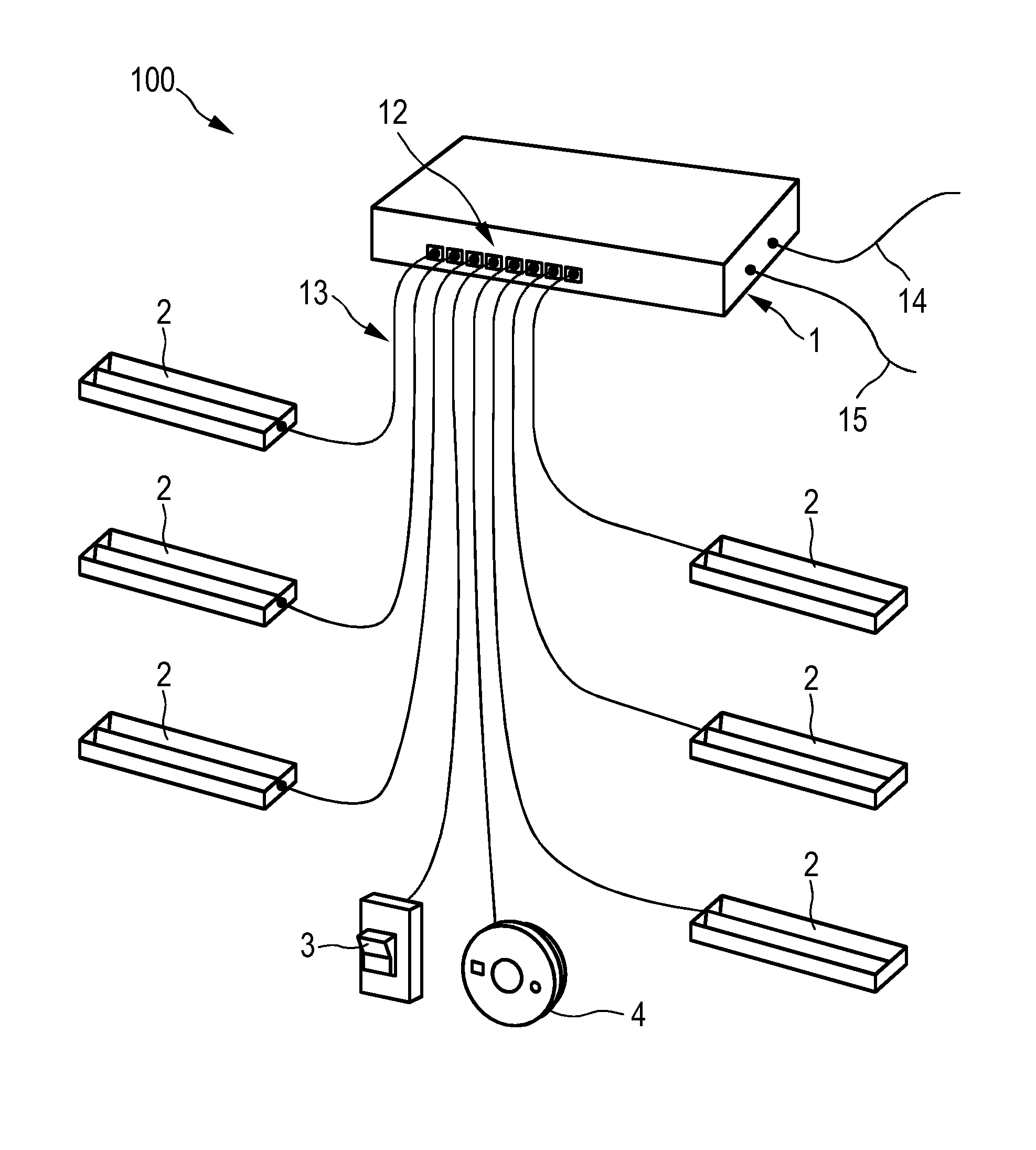
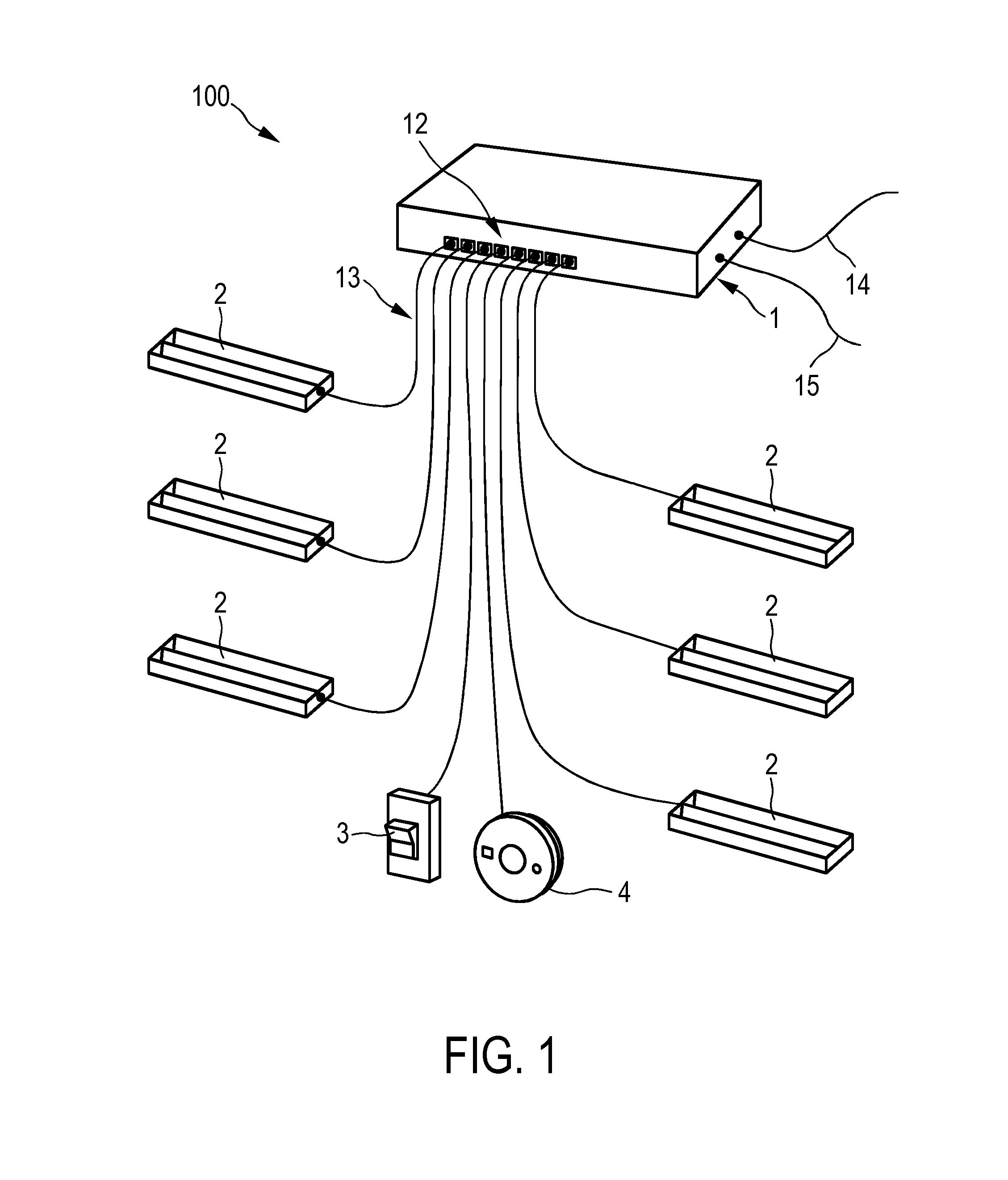
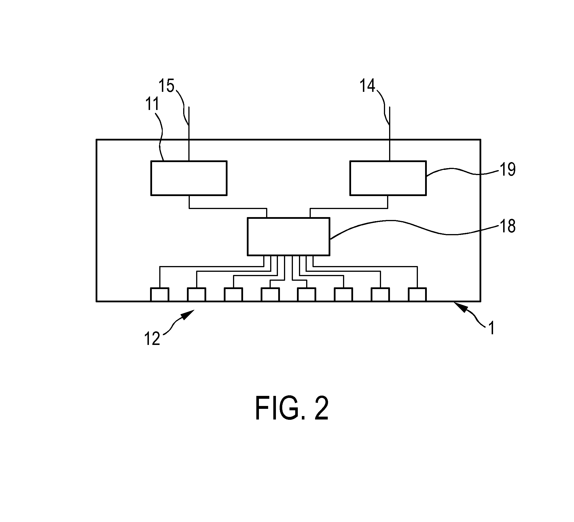
[0035]FIG. 1 shows schematically and exemplarily an embodiment of a power distribution system 100 comprising a power sourcing device 1 for sourcing a power to powered devices 2, 3, and 4. In this embodiment, the power distribution system 100 is a PoE system and the power sourcing device 1 is a switch. The power sourcing device 1 is schematically and exemplarily shown in more detail in FIG. 2.

[0036]The power sourcing device 1 comprises several ports 12 to which the powered devices 2, 3, and 4 are connected via Ethernet cables 13, which are adapted to convey the sourced power along with data. The power sourcing device 1 receives an input power via an electrical connection 15 that may be directly connected to a mains outlet (not shown in the figure), and the data may be received from another device (not shown in the figure), e.g., another switch, via another Ethernet cable 14. From the received power, a power supply unit 11 generates the power to be sourced to the powered devices 2, 3,...


PUM


Abstract

The invention relates to a powered device (2) like a luminaire for being used in a power distribution system (100), which is preferentially a PoE system and which comprises a power sourcing device (1) for sourcing a power to the powered device. The powered device comprises an electrical load like an LED and an electrical load power providing unit for generating from the sourced power an electrical load power and for providing the electrical load power to the electrical load, wherein the electrical load power providing unit is adapted to generate the electrical load power with a power level such that an input current drawn by the powered device from the power sourcing device is maximized below a predefined upper input current threshold. This allows increasing the power consumption of the powered device in comparison to the power consumption of powered devices in accordance with the PoE standard IEEE 802.3at.

Description

FIELD OF THE INVENTION[0001]The present invention relates to a powered device for being used in a power distribution system, the system comprising a power sourcing device for sourcing a power to the powered device and an electrical conductor connected to the power sourcing device and the powered device for conveying the sourced power along with data between the power sourcing device and the powered device. The present invention further relates to a power distribution system comprising the powered device, and to a method and computer program for providing an electrical load power to an electrical load of the powered device.BACKGROUND OF THE INVENTION[0002]In Power-over-Ethernet (PoE) systems in accordance with the PoE standard IEEE 802.3at, a power sourcing device (power sourcing equipment; PSE) sources a power to one or several powered devices (PD) via one or several Ethernet cables. The power sourcing device is, e.g., a switch and the powered devices are, e.g., security cameras, wi...

Claims


Application Information

Patent Timeline
Patent Type & Authority Applications(United States)
IPC IPC(8): H04L12/10G06F1/26
CPCG06F1/266H04L12/10H05B47/18
Inventor YSEBOODT, LENNARTWENDT, MATTHIAS
Owner SIGNIFY HLDG BV
Why Eureka
Try Eureka