Feedback-type amplifier circuit and driver circuit

a driver circuit and amplifier circuit technology, applied in the direction of electric variable regulation, process and machine control, instruments, etc., can solve the problems of increasing power consumption, further increasing power consumption, and the feedback-type amplifier circuit of the conventional type (operational-amplifier type) cannot achieve high-speed, stabilized drive, etc., to achieve the effect of suppressing the vibration of an output waveform

Inactive Publication Date: 2003-09-02
RENESAS ELECTRONICS CORP
View PDF4 Cites 83 Cited by
  • Summary
  • Abstract
  • Description
  • Claims
  • Application Information

AI Technical Summary

Benefits of technology

The larger the phase compensating capacitance, the more stable operation becomes. The higher the operating speed is made, therefore, the larger the phase compensating capacitance that must be provided. This leads to a further increase in power consumption.
Accordingly, it is an object of the present invention to provide a driver circuit in which output voltage Vout can be driven to a level equal to input voltage Vin at high speed with little operation maintaining current, and in which even a large capacitance load can be driven at high speed with low power consumption because operation is not accompanied by needless charging and discharging, thus making it possible to implement high-performance operation.
It is another object of the present invention to provide a driver circuit which is capable of suppressing vibration of an output waveform of the driver circuit in such a case of driving for example a large capacitance load or the like.
In a feed-back type amplifier circuit in accordance with the present invention, there may be provided a capacitor between an output of an differential pair constituting a feed-back type charging means and output terminal for suppressing vibration of an output waveform.

Problems solved by technology

This results in an increase in power consumption.
This leads to a further increase in power consumption.
A feedback-type amplifier circuit of the conventional type (operational-amplifier type) cannot achieve high-speed, stabilized drive with little consumption of power.

Method used


Image

  • Feedback-type amplifier circuit and driver circuit
  • Feedback-type amplifier circuit and driver circuit
  • Feedback-type amplifier circuit and driver circuit

Examples


first embodiment

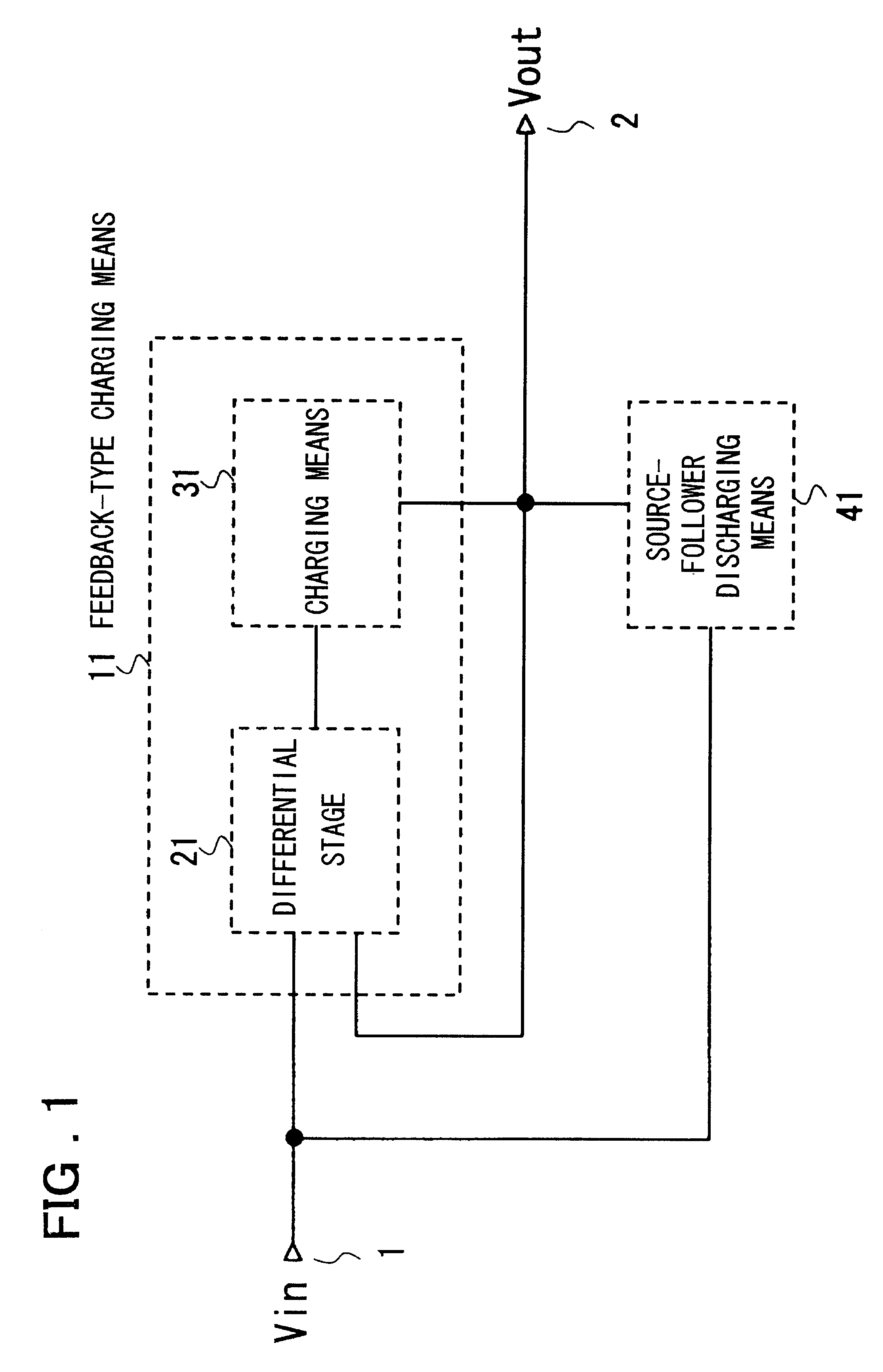
FIG. 1 is a block diagram illustrating the structure of the present invention.

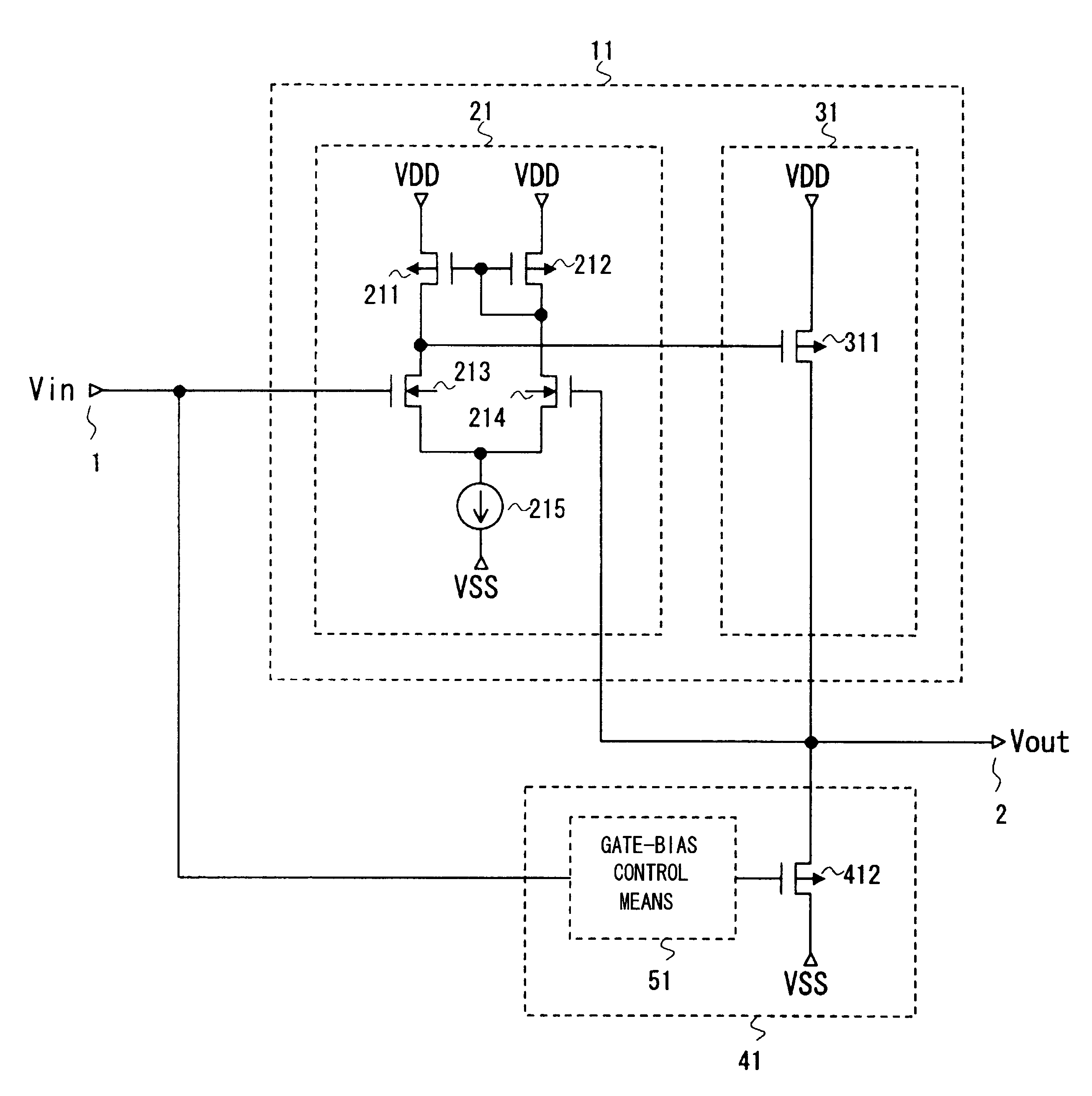
As shown in FIG. 1, the circuit according to the first embodiment of the invention comprises feedback-type charging means 11, which is capable of pulling up an output voltage Vout by producing a charging effect by the two inputs applied thereto, i.e., the input voltage Vin and output voltage Vout, and source-follower discharging means 41 which, through an operation independent from that of the feedback-type charging means 11, is for producing a discharging effect based upon the source-follower operation of a transistor in accordance with a voltage difference between the input voltage Vin and output voltage Vout.

The feedback-type charging means 11 has a differential stage 21, which operates in accordance with a voltage difference between the input voltage Vin and output voltage Vout, and charging means 31 for producing a charging effect in dependence upon the output of the differential stage 21.

This embodim...

second embodiment

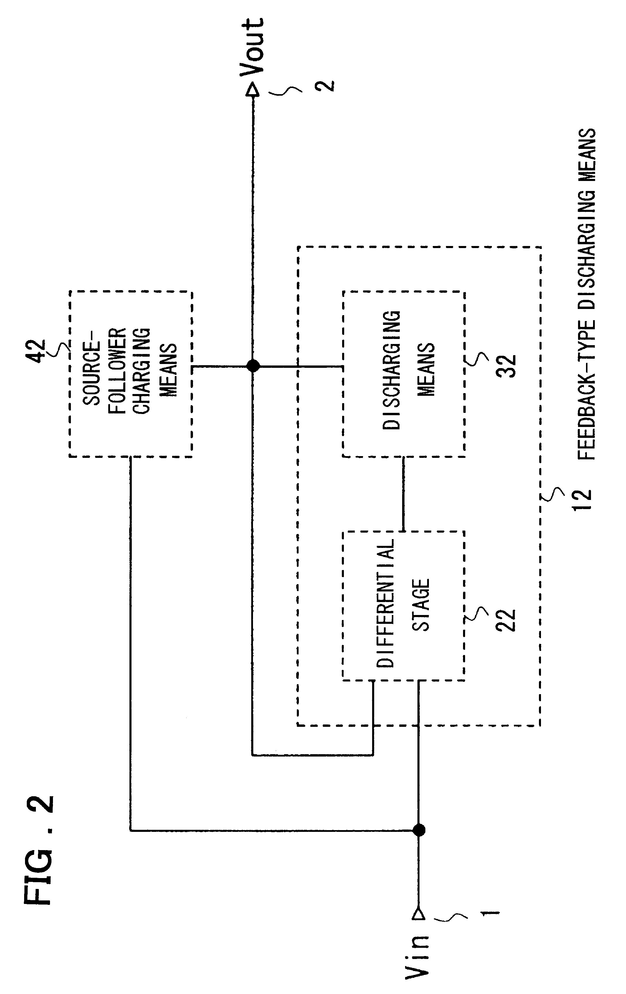
FIG. 2 is a block diagram illustrating the structure of the present invention.

As shown in FIG. 2, the circuit according to the second embodiment of the invention comprises feedback-type discharging means 12, which is capable of pulling down the output voltage Vout by producing a discharging effect by the two inputs applied thereto, i.e., an input voltage Vin and output voltage Vout, and source-follower charging means 42 which, through an operation independent from that of the feedback-type discharging means 12, is for producing a charging effect based upon the source-follower operation of a transistor in accordance with a voltage difference between the input voltage Vin and output voltage Vout.

The feedback-type discharging means 12 has a differential stage 22, which operates in accordance with a voltage difference between the input voltage Vin and output voltage Vout, and discharging means 32 for producing a discharging effect in dependence upon the output of the differential stage ...


PUM


Abstract

Disclosed is a feedback-type amplifier circuit including feedback-type charging means, which operates as a voltage follower, having a differential stage which receives an input-terminal voltage and an output-terminal voltage differentially as inputs and charging means for performing a charging operation at the output terminal based upon an output from the differential stage; and follower-type discharging means for performing a discharging operation at the output terminal by follower operation of an active element in accordance with a voltage difference between the input-terminal voltage and the output-terminal voltage.

Description

This invention relates to an amplifier and a driver circuit for driving a capacitive load to a desired voltage. More particularly, the invention relates to a driver circuit capable of driving a data line of a capacitive load at a high speed with low power consumption in an active matrix display device (such as a TFT-LCD or TFT-OLED, etc.).FIGS. 33A and 33B are diagrams illustrating conventional circuit structures of simplest feedback-type charging means. As shown in FIG. 33A, the charging means includes N-channel MOS transistors 903 and 904 constituting a differential pair in which the sources are coupled together and connected to one end of a constant-current source 905 and gates are connected to an input terminal 1 (Vin) and an output terminal 2 (Vout), respectively; a P-channel MOS transistor 901 (a transistor on the current output side of a current mirror) having its source connected to a higher-side potential power supply VDD, its gate connected to the gate of a P-channel MOS t...

Claims


Application Information

Patent Timeline
Patent Type & Authority Patents(United States)
IPC IPC(8): H03F3/50G09G3/36G09G3/20H03F1/32H03F3/45
CPCH03F3/505H03F1/32
Inventor TSUCHI, HIROSHI
Owner RENESAS ELECTRONICS CORP
Why Eureka
Try Eureka