
Cable and method for manufacturing a synthetic cable

Active Publication Date: 2016-06-16
BRASKEM SA
View PDF9 Cites 8 Cited by
  • Summary
  • Abstract
  • Description
  • Claims
  • Application Information

AI Technical Summary

Benefits of technology

The present invention provides a synthetic cable with a core made of high modulus threads arranged in parallel and splice-type termination ends. The splices are made of high modulus threads arranged in parallel to form an eyelet on each splice. The threads of each splice and the core are arranged in parallel at an interpenetration region. The cable has an interlaced structure at the splicing points, which increases its strength and durability. The method for manufacturing the cable involves individually connecting each leg of the threads with a thread of the cable core, straining all the threads, applying a normal compression force at the interpenetration region of the splice, and applying at least one protective element along the entire length of the cable. The technical effect of the invention is to provide a strong and durable synthetic cable with high modulus threads arranged in parallel that can withstand high tensile and bending loads.

Problems solved by technology

However, technical and logistic difficulties associated with the depth and distance from the shore has brought new technological challenges.
Although said materials have greater performance than polyester, the use of classical construction technologies currently used by thread industries has resulted in low efficiency on the cables, which is aggravated by the increased diameter that is proportional to the maximum break load (MBL).
The low efficiency related to the construction aspects from the state of the art requires the use of a larger amount of threads for an intended MBL to be achieved, reducing the price competition of these materials over the use of polyester.
The first one is related with the reduction in the strength of the threads due to high wear and loss of material on the walls of the filaments during the production process of the cable.
This operation also implies several problems in aligning and controlling the stress of threads on the seam or splice.
Intrinsically, the two latter aspects explaining the low efficiency of cables made of high modulus threads are interrelated with each other, wherein these aspects have as the main cause the low elongation of high modulus threads resulting in an intolerance to local mobility differences.
That is, the different paths among the thousands of threads jeopardize mobility thereof, overloading regions of the cable during tensile assays or use under extreme situations.
This effect is even worse in the regions were splices are seamed and therefore on these regions there is a probability for the cable to break.
However, with the technology known from the state of the art the construction in parallel precludes the use of splice-type terminations, as the hand seaming of the splice threads to the cable body is practically impossible.
However, for cables of high MBL (used in applications of production platforms and offshore drilling rigs, for example, the tensile strength ranges from 600 to 1250 tf), the local stresses between the cable body and the terminations are huge, and in this case, using a mechanical clamp is certainly not possible.
That is, unless the connection can be made homogeneously over the entire cross section area surface of the cable, it is much harder to obtain an effective terminal in cables of high diameter as compared to those of low diameter.
However, in practice, when high MBL values are being obtained, sockets become inefficient, considering that in this type of terminal a few millimeters of filament-resin interaction are needed for the adhesion strength to overcome the thread breaking strength as widely known, and also reported by Mckenna, 2004.
The result is the gradual detachment of the thread-resin interface resulting in local stress concentration and consequent breakage of the filaments.
However, the disadvantage of this type of structure is that the cable body has twice the number of yarns than its terminations.
That is, the greater likelihood of fracture is on the terminations, which makes it impossible to be used on very high load applications, as is the case of for example of anchorage cables.
However, these documents do not describe how to manufacture the terminations.
Nevertheless, as mentioned before, a problematic aspect of this technology is how the termination ends are connected.
However, since the tensile strength of the cable is mainly in the form of shear and compression forces onto yarns of the ends, the lower the thread strength in the crosswise direction, the worse the performance of this type of device.
An example is the HMPE thread which has an Young's modulus and a tensile strength comparable to a steel cable; however, this type of thread has low shear strength and transverse compression.
Therefore, using this type of device in high modulus threads would not result in good efficiency, especially when high failure load (or high MBL) cables are to be manufactured.
However, the document does not disclose results on the efficiency of the tested cables.
Another important issue related to this document is the applicability of such hybrid construction when using steel and HMPE.
HMPE has a more pronounced flowability problem as compared to other synthetic yarns.
Thus, even with recent advances in this respect (as shown in patent document WO 2012 / 139934), such a problem would make long term applications impossible—which is the case of oil platforms anchorage.
The tensile strength would cause the steel threads to overload with time and under an extreme condition (as is the case of a severe storm), the structure would probably collapse.

Method used


Image

  • Cable and method for manufacturing a synthetic cable
  • Cable and method for manufacturing a synthetic cable
  • Cable and method for manufacturing a synthetic cable

Examples


Embodiment Construction

[0037]The following description will be based on a preferred embodiment of the invention. As will be evident to the skilled person, however, the invention is not restricted to this particular embodiment.

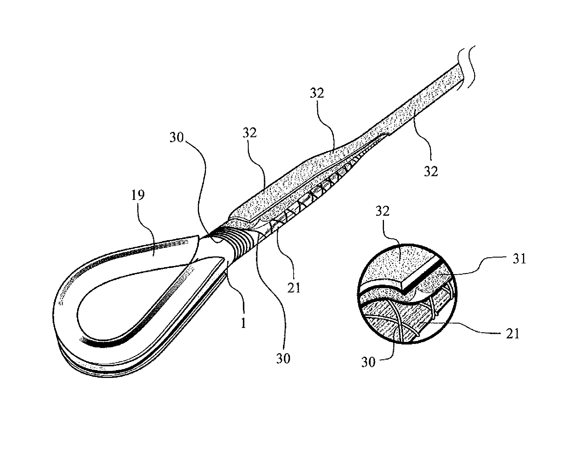
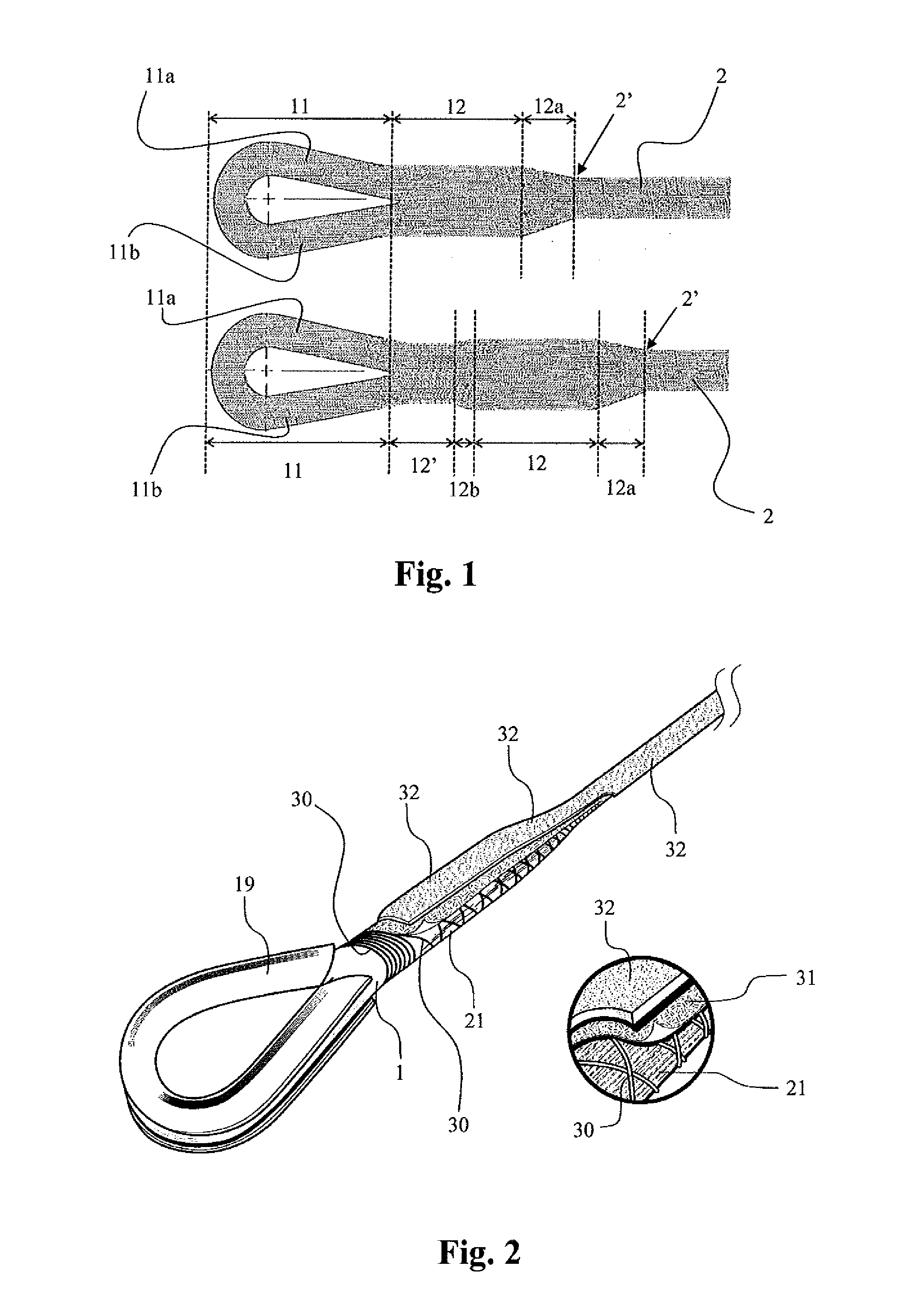
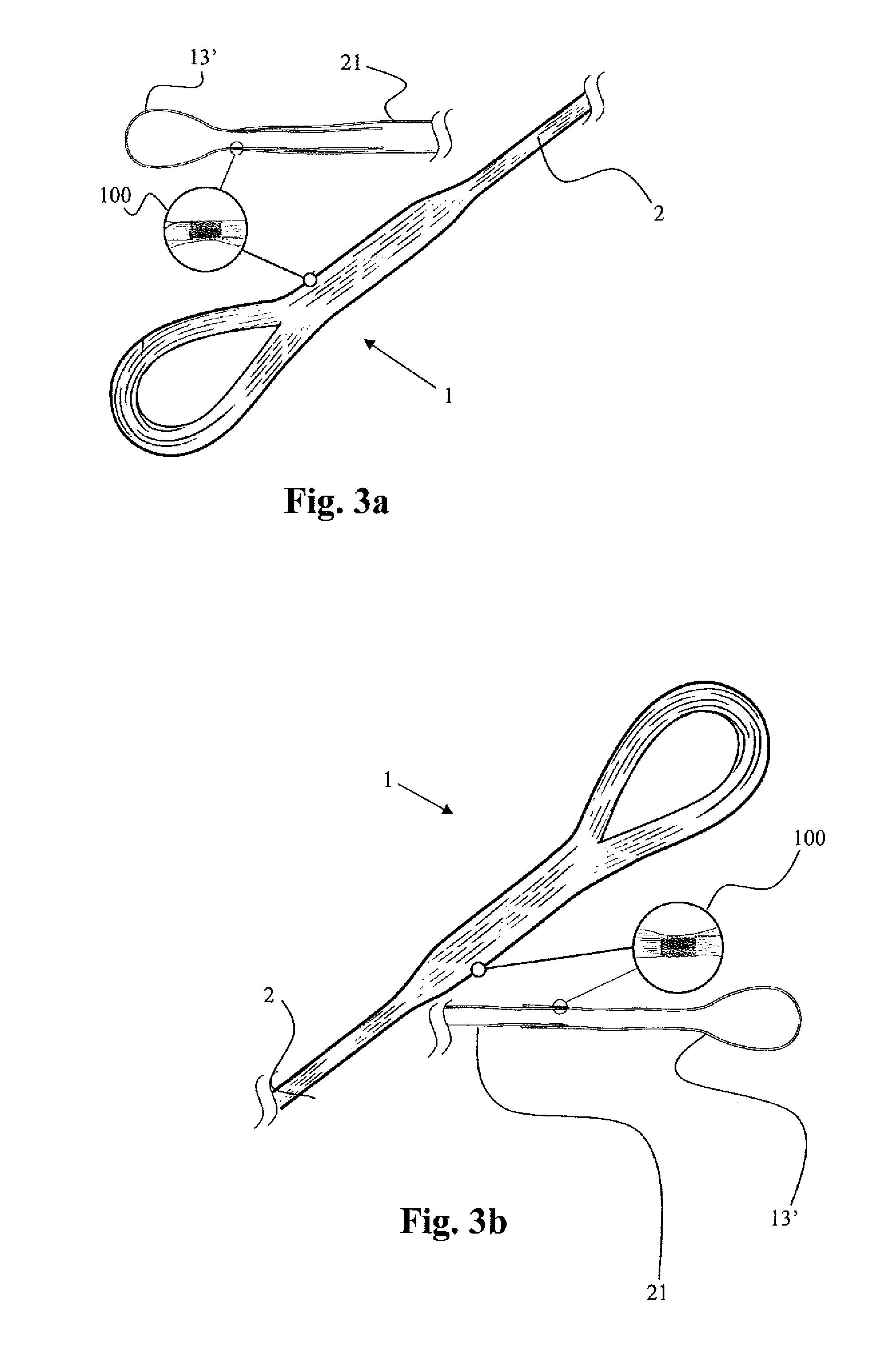
[0038]The present invention is directed to a cable 2 containing a core where threads 21 are arranged in a single bundle of parallel structure connected to a splice 1 by a region, referred to as interpenetration region 12, where the splice threads 13,13′ and the core threads 21 are arranged in parallel to each other.

[0039]The cable 2 disclosed herein is ideal for applications that require an optimum relationship between MBL and efficiency as is the case of the use of offshore anchorage lines. The performance thereof in applications with high level of mechanical requirements provides significant potential gains also in terms of transportation logistics and cost of installation, in addition to allowing the potential reduction in the number of anchorage lines, enabling a potential increa...


PUM

PropertyMeasurementUnit
Lengthaaaaaaaaaa
Forceaaaaaaaaaa
Flexibilityaaaaaaaaaa

Abstract

The present invention relates to synthetic cables comprising a core formed of high modulus threads arranged in parallel to each other, wherein the ends of the cable comprise splice-type termination ends (1), wherein each splice (1) comprises high modulus threads arranged in parallel to each other forming an eyelet (11) on each splice, wherein each leg of the threads (13, 13) comprising each splice is connected to a thread (21) that forms the core of the cable, wherein the splice threads (13, 13) and the core threads are arranged in parallel to each other at an interpenetration region (12).The present invention further discloses a method for manufacturing a synthetic cable comprising a core formed of high modulus threads arranged in parallel to each other, wherein the ends of the cable comprise splice-type termination ends (1), wherein each splice (1) comprises high modulus threads arranged in parallel to each other, which method comprises the steps of: individually connecting each leg of the threads (13) comprising a positive splice to a thread (21) of the beginning end of the cable core (2) forming a loop; joining the threads of the positive splice (13) so as to form a loop, straining all the threads, wherein the splice threads (13) and the core threads (21) are arranged in parallel to each other at an interpenetration region (12); applying a normal compression force at the interpenetration region (12) of the positive splice (1); applying at least one protective element (32) along the entire length of the cable; individually connecting each leg of the threads (21) that form a negative splice to a thread (21) of the final end of the cable core (2) forming a loop; joining the threads (13) of the positive splice so as to form a loop, straining all the threads, wherein threads (31) from the splice and threads (21) from the core are arranged in parallel to each other at an interpenetration region (12); and applying a normal compression force at the interpenetration region (12) of the negative splice.

Description

TECHNICAL FIELD[0001]The present invention relates to a cable comprising a core formed by high modulus threads arranged in parallel and connected to a splice-type termination end.DESCRIPTION OF THE STATE OF THE ART[0002]The history of oil and gas exploitation in offshore reservoirs has been accompanied by extensive technological development since deeper waters are being exploited. Replacement of steel cables with synthetic wires that has occurred during the 90's has enabled an advancement into deep and ultra deep waters. Discovery of new reservoirs in pre-salt layers as reported by Petrobras in 2006, has given Brazil an important role in the world market, changing the International energy matrix. However, technical and logistic difficulties associated with the depth and distance from the shore has brought new technological challenges.[0003]Aspects such as difficulty in the transportation of anchorage lines, the environmental forces involved and the need for a strict restriction of t...

Claims


Application Information

Patent Timeline
IPC IPC(8): D07B1/18D07B9/00D07B7/16
CPCD07B1/185D07B9/00D07B7/169D07B1/025D07B3/00D07B5/002D07B2201/2033D07B2201/2034D07B2201/2098D07B7/167D07B1/02D07B1/18D07B7/16D07B5/00
Inventor BUENO, MARCOS ROBERTO PAULINOPENAQUIONI, ANDRE
Owner BRASKEM SA
Learn More