Electroplating apparatus with membrane tube shield

Active Publication Date: 2016-07-21
APPLIED MATERIALS INC
View PDF5 Cites 0 Cited by
  • Summary
  • Abstract
  • Description
  • Claims
  • Application Information

AI Technical Summary

Benefits of technology

[0005]An electroplating apparatus has one or more membrane tube rings which act as electric field shields, to provide advantageous plating characteristics at the perimeter of a substrate. The membrane tube rings may be filled with flu

Problems solved by technology

Achieving a uniformly thick plated metal film can be difficult, for various reasons.
In Damascene plating, the sheet resistance of the film changes duri

Method used


Image

  • Electroplating apparatus with membrane tube shield
  • Electroplating apparatus with membrane tube shield
  • Electroplating apparatus with membrane tube shield

Examples


Embodiment Construction

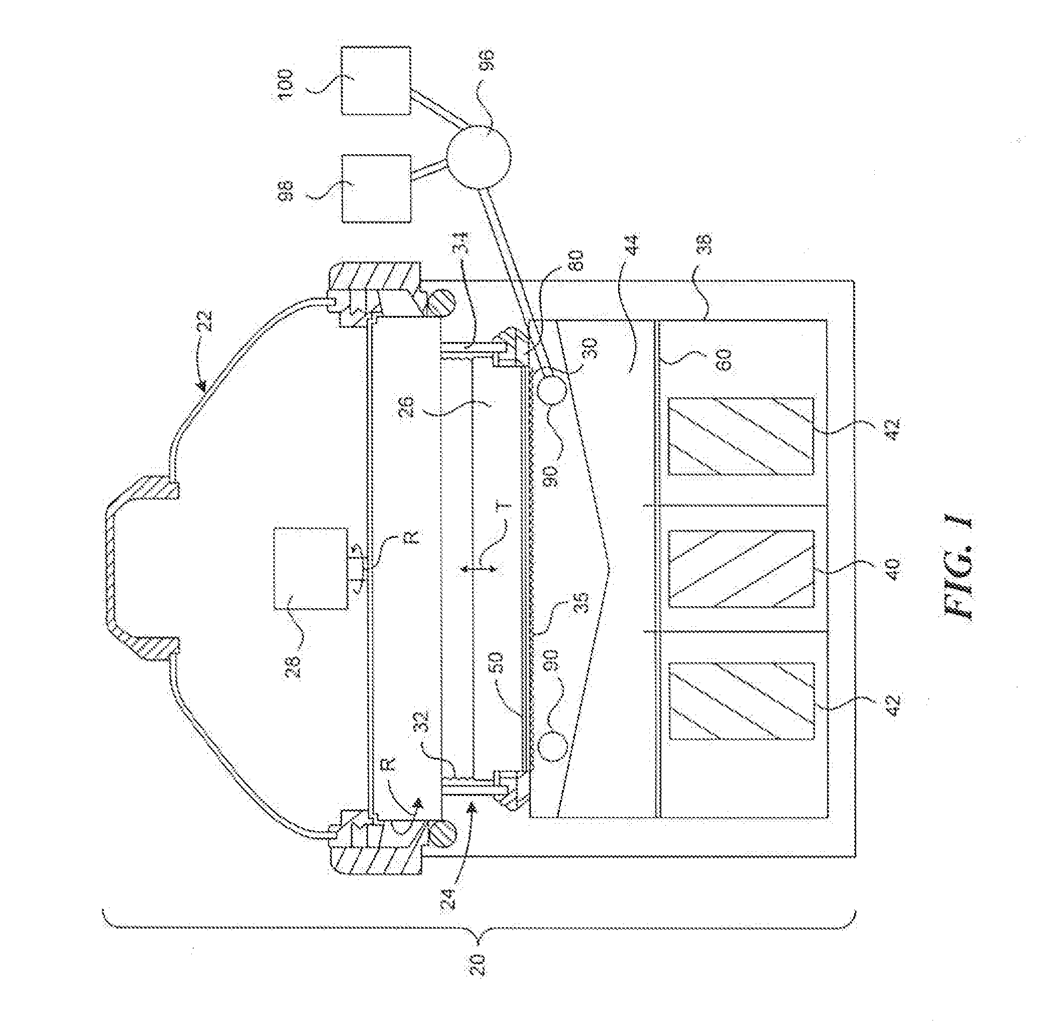
[0008]In FIG. 1, an electroplating apparatus 20 has a rotor 24 in a head 22. The rotor 24 includes a backing plate 26 and a contact ring 30 having a seal ring 80. Contact ring actuators 34 move the contact ring 30 vertically (in the direction T in FIG. 1), to engage the contact ring 30 and the seal ring 80 onto the down facing surface of a wafer or substrate 50. A bellows 32 may be used to seal internal components of the head.

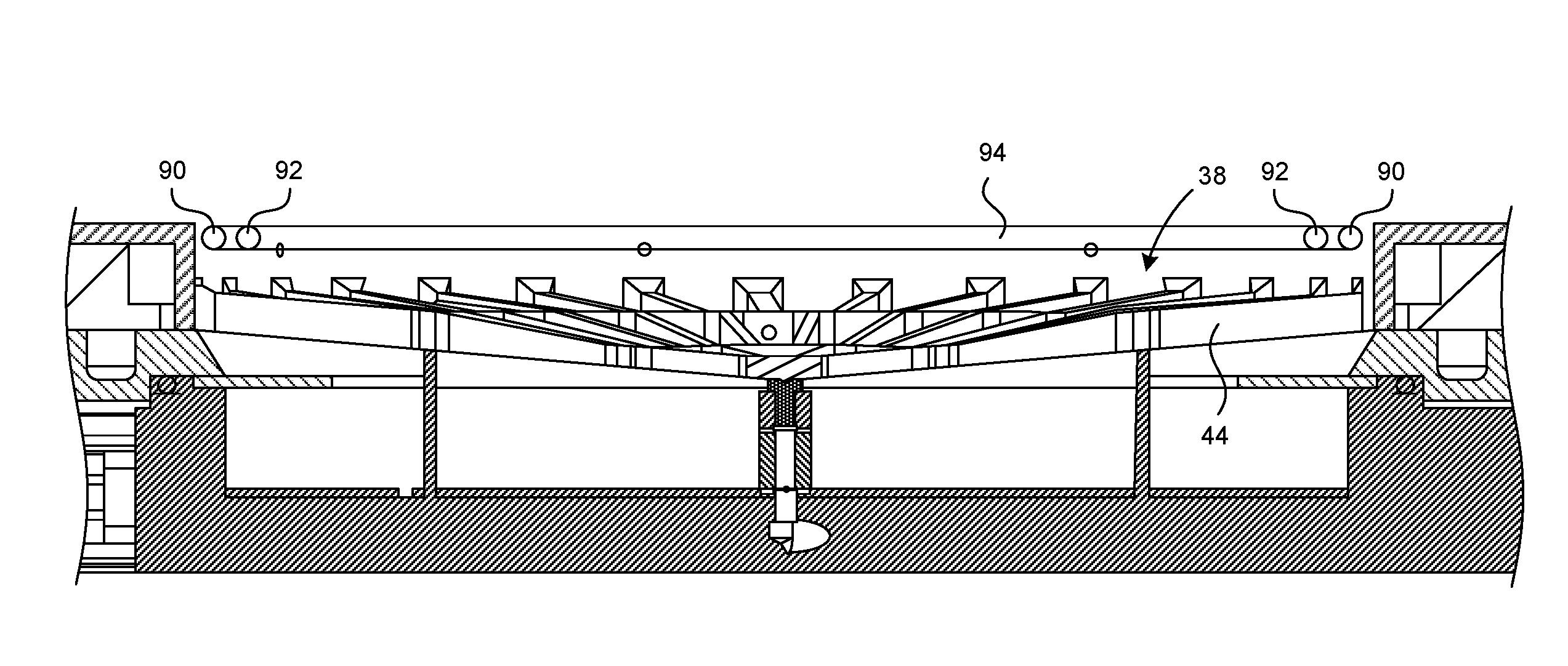
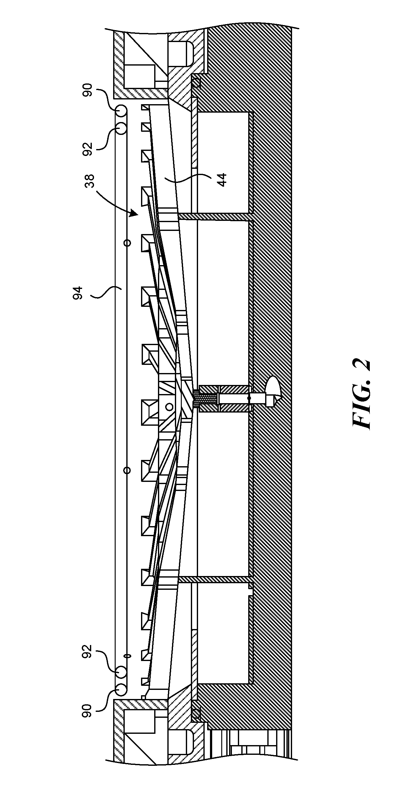
[0009]The contact ring typically has metal fingers 35 that contact a conductive layer on the substrate 50. In FIG. 1, the head 22 is shown positioned to place the substrate 50 in a process position, where the substrate is in contact with the bath of liquid electrolyte held in a vessel 38. For processing a 300 mm diameter substrate, the vessel may have a diameter of 305 to 380 mm.

[0010]FIG. 1 shows a design having a center electrode 40 surrounded by a single outer electrode 42, although multiple concentric outer electrodes may be used. A single electrode may als...


PUM

PropertyMeasurementUnit
Diameteraaaaaaaaaa
Diameteraaaaaaaaaa
Dielectric polarization enthalpyaaaaaaaaaa

Abstract

An electroplating apparatus has one or more membrane tube rings which act as electric field shields, to provide advantageous plating characteristics at the perimeter of a work piece. The membrane tube rings may be filled with fluids having different conductivity, to change the shielding effect as desired for electroplating different types of substrates. The membrane tube rings may optionally be provided in or on a diffuser plate in the vessel of the apparatus.

Description

BACKGROUND OF THE INVENTION[0001]Manufacture of microelectronic devices and other micro-scale devices typically requires formation of multiple metal layers on a wafer or other substrate. By electroplating metals layers in combination with other steps, patterned metal layers forming the micro-scale devices are created.[0002]The substrate is electroplated in a plating apparatus or chamber, with one side of the substrate in a bath of liquid electrolyte, and with electrical contacts touching a conductive layer on the substrate surface. Electrical current is passed through the electrolyte and the conductive layer. Metal ions in the electrolyte plate out onto the substrate, forming a metal film on the substrate. To better achieve uniform plated film thickness, the plating apparatus may have an annular dielectric shield, which shields or reduces the electric field in the electrolyte near the edge of the substrate.[0003]Achieving a uniformly thick plated metal film can be difficult, for var...

Claims


Application Information

Patent Timeline
IPC IPC(8): C25D5/00
CPCC25D5/00C25D17/001C25D17/007C25D17/008C25D17/12C25D17/002C25D5/04
Inventor MCHUGH, PAUL R.WILSON, GREGORY J.SHAVIV, ROEY
Owner APPLIED MATERIALS INC
Why Eureka
Try Eureka