Centrifugal separator and rotor

Active Publication Date: 2013-04-18
ALFA LAVAL CORP AB
View PDF5 Cites 4 Cited by
  • Summary
  • Abstract
  • Description
  • Claims
  • Application Information

AI Technical Summary

Benefits of technology

[0004]An object of the present invention is to propose a centrifugal separator which allows

Problems solved by technology

The conical shape also results in self-centering of the rotor on the rotor shaft.
Such dismantling is relatively time-consuming.
Such large

Method used


Image

  • Centrifugal separator and rotor
  • Centrifugal separator and rotor
  • Centrifugal separator and rotor

Examples


Example

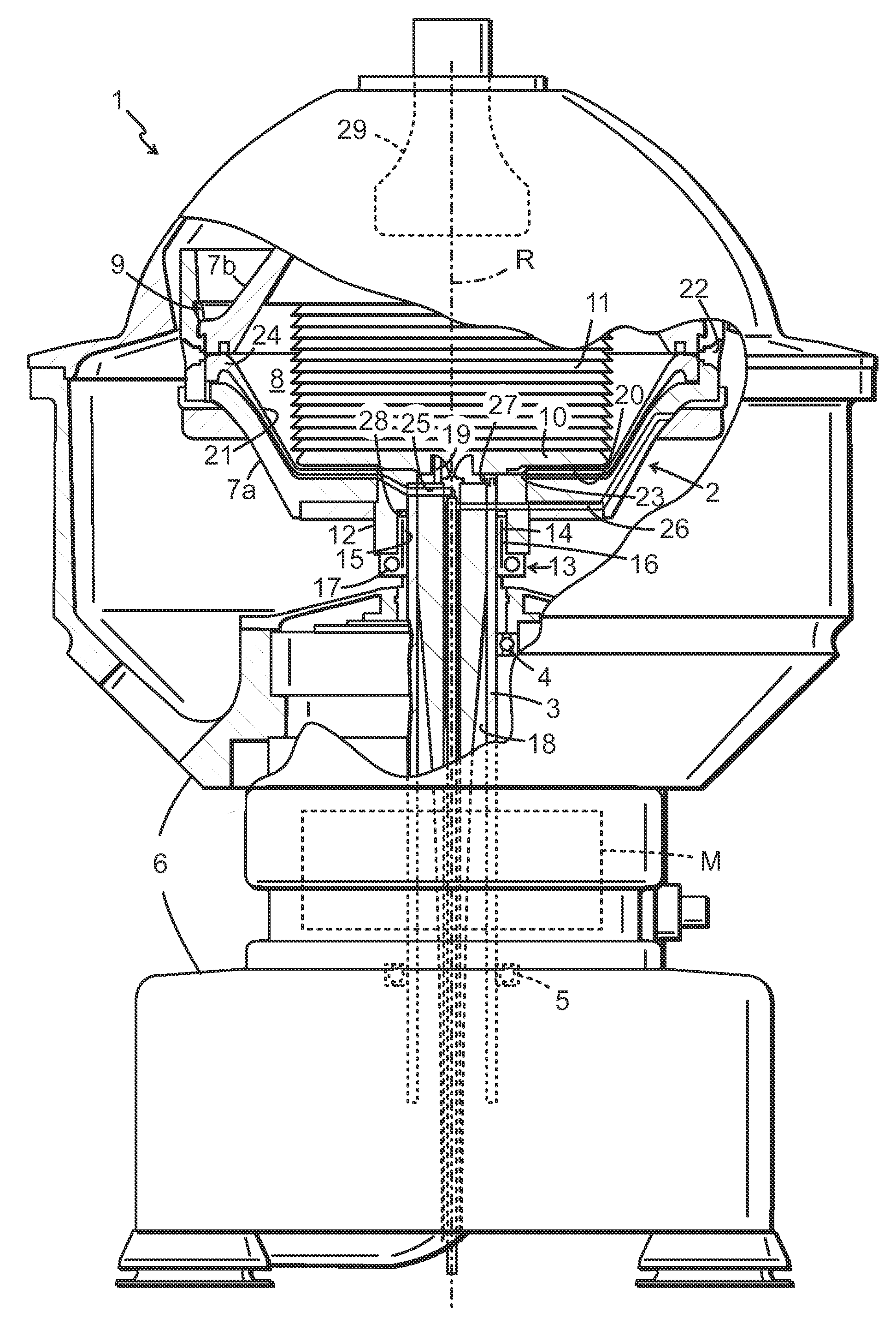
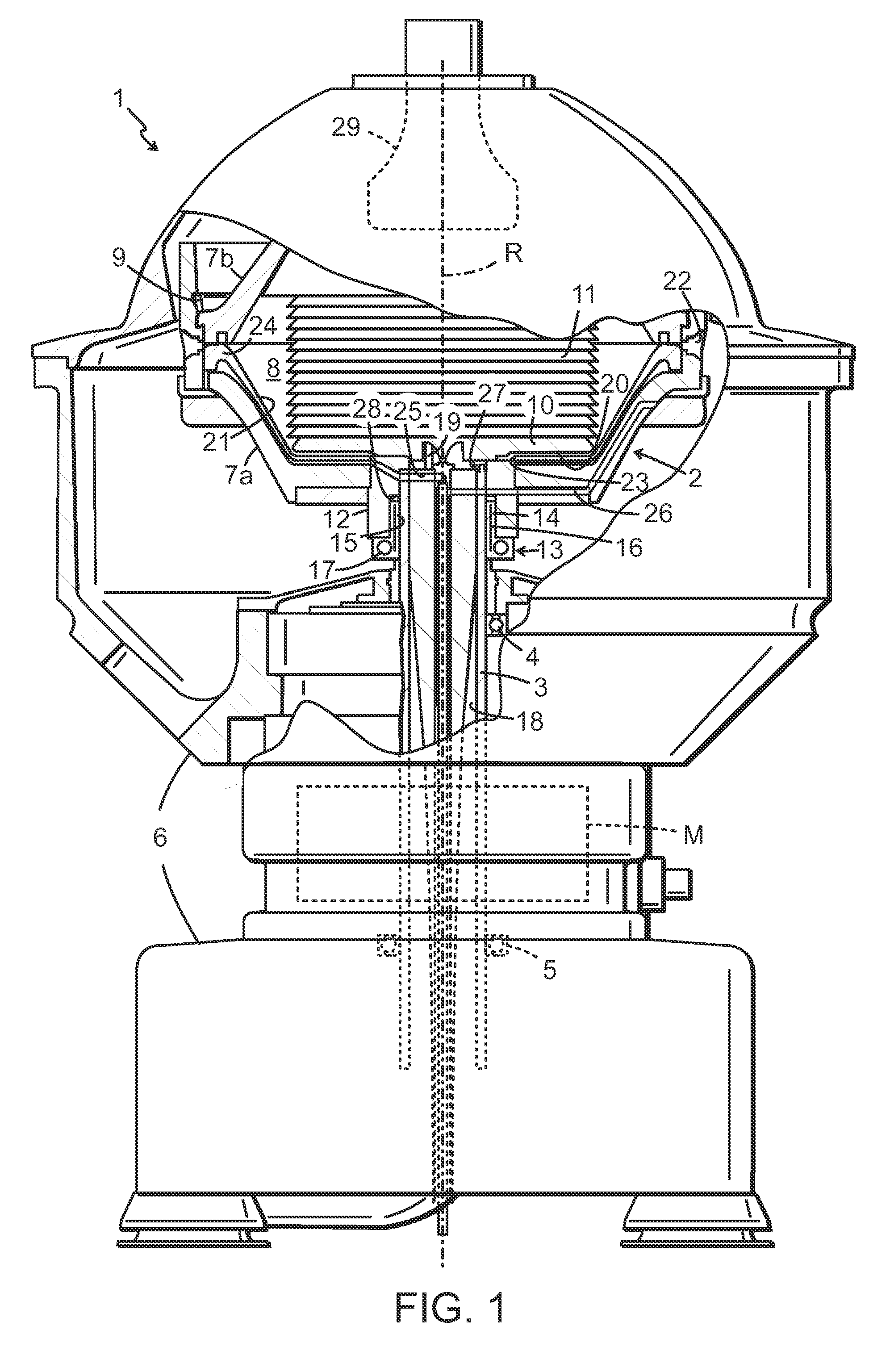
[0023]FIG. 1 shows a centrifugal separator 1 according to a first embodiment of the invention. The centrifugal separator 1 comprises a rotor 2 situated uppermost on a vertical rotor shaft 3. The rotor shaft 3 is journalled by an upper bearing (a so-called top bearing 4) and a lower bearing (a so-called bottom bearing 5) in a frame 6. The rotor shaft 3 is thus arranged to support the rotor 2 for rotation about a vertical axis of rotation R in the frame 6. A motor M is adapted to driving the rotor 2 about the axis of rotation R. The rotor 2 has a rotor wall 7a, 7b which surrounds an inner space with a separating chamber 8 in which the main centrifugal separation takes place. The inner space also comprises other spaces within the rotor, e.g. inlet passages for the mixture which is to be separated in the separation space 8, and at least one outlet chamber for a separated component. The rotor wall is divided into a lower part 7a and an upper part 7b which are held together by a locking r...

Example

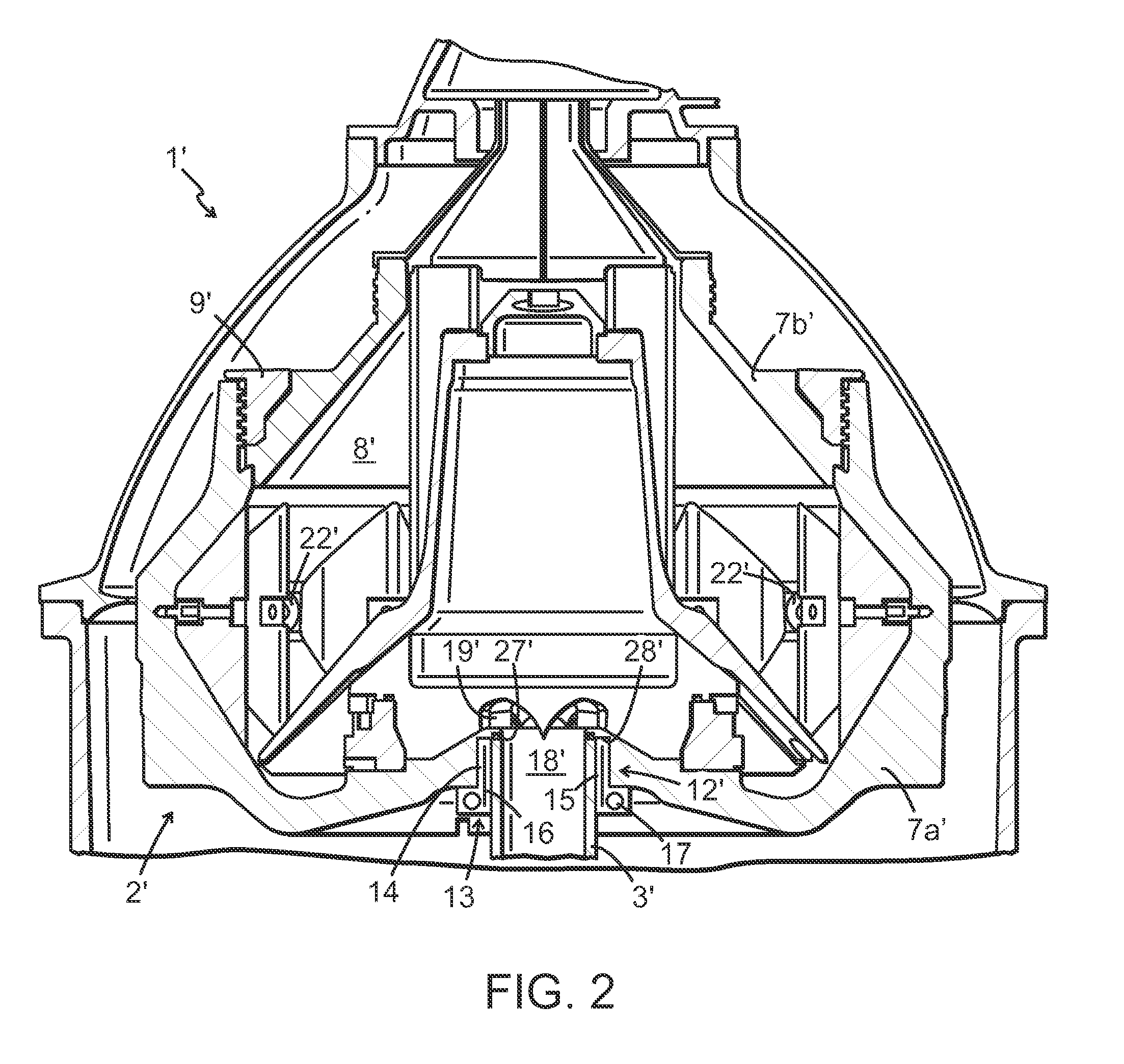
[0029]FIG. 2 shows a centrifugal separator 1′ according to a second embodiment of the invention. It should be noted that constituent parts which have the same or similar functions are designated by the same reference signs in both embodiments. This centrifugal separator 1′ differs from the centrifugal separator according to FIG. 1 inter alia in the configuration of the hub 12′. This hub 12′ takes the form of a recess in the lower part 7a′ of the rotor wall. The recess is formed in a relatively thick rotor wall 7a′. The recess 12′ may therefore be made deep enough, with no need for the hub to extend axially inwards in the rotor 2′. The recess 12′ is configured to radially surround a portion of the rotor shaft 3′, and a clamping device 13 is provided to connect the hub to said portion of the rotor shaft 3′. This involves the clamping device 13 being fitted in an annular space arranged radially between the hub 12′ and the rotor shaft 3′. The clamping device 13 has in this embodiment th...


PUM


Abstract

The invention relates to a centrifugal separator for separation of at least two components of a fluid mixture which have different densities. The centrifugal separator comprises a rotor arranged for rotation about a vertical axis of rotation (R) and having a rotor wall which surrounds a separating chamber within the rotor, with an inlet adapted to feeding the fluid mixture into the rotor's separating chamber, and at least one outlet adapted to discharging outwardly from the rotor a component separated from the fluid mixture. A rotor shaft supports the rotor and is drivably connected to a motor (M) for rotation of the rotor about the axis of rotation (R). A hub is provided outside the rotor, and the hub and the rotor shaft are arranged to be connected together from the outside of the rotor by means of a lockable and releasable fastening which is configured to lock the rotor shaft relative to the hub in both a torque-transmitting and an axial force-transmitting way.

Description

TECHNICAL FIELD[0001]The invention relates to a centrifugal separator for separation of two or more components of a fluid mixture which are of different densities. The centrifugal separator comprises a rotor which is rotatable about an axis of rotation. The rotor comprises a rotor wall which surrounds an inner space with a separating chamber within the rotor, with an inlet adapted to feeding the fluid mixture into the rotor's separating chamber and at least one outlet adapted to discharging out from the rotor a component separated from the fluid mixture. A rotor shaft is arranged to be connected to a hub on the rotor wall, and the rotor is supported via the rotor shaft which is drivably connected to a motor for rotation of the rotor about the axis of rotation. The invention relates also to the actual rotor for the aforesaid centrifugal separator.BACKGROUND OF THE INVENTION[0002]Certain types of centrifugal separators have a rotor that is situated on an uppermost portion on a vertica...

Claims


Application Information

Patent Timeline
IPC IPC(8): B04B7/08
CPCB04B1/08B04B1/14B04B2009/085B04B9/08B04B7/08F16D1/08
Inventor ISAKSSON, ROLANDTHORWID, PETER
Owner ALFA LAVAL CORP AB
Why Eureka
Try Eureka