Electronic vaporization devices

a technology of electronic vaporization and vaporization chamber, which is applied in the direction of ohmic resistance heating, ohmic resistance heating details, tobacco, etc., can solve the problems of engineering challenges, too small aerosol particles in this size range to gravitate into the lung during regular breathing, etc., and achieve the effect of efficient delivery

Active Publication Date: 2016-07-28
FONTEM VENTURES
View PDF11 Cites 107 Cited by
  • Summary
  • Abstract
  • Description
  • Claims
  • Application Information

AI Technical Summary

Benefits of technology

[0010]The device may include a flow sensor electrically connected to an electronic controller which receives and stores an inhalation profile of a user of the device, with the device configured to modify a characteristic of the device based on the inhalation profile. The device may further include a user interface config

Problems solved by technology

Aerosol particles in this size range can be too small to gravitationally settle in the lung during regular breathing.
These factors create engi

Method used


Image

  • Electronic vaporization devices
  • Electronic vaporization devices
  • Electronic vaporization devices

Examples


Embodiment Construction

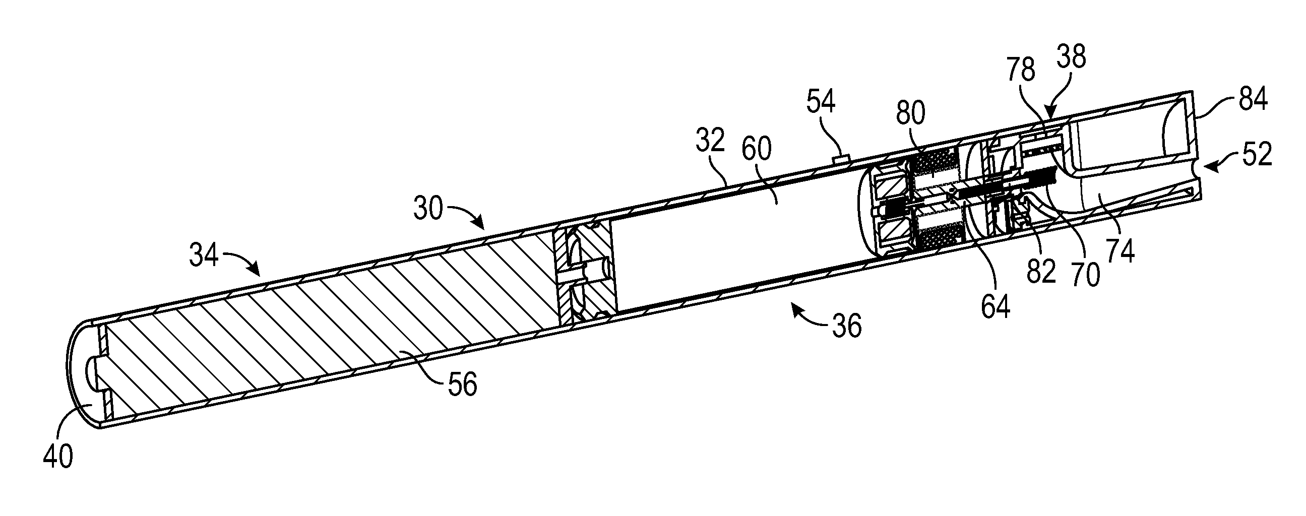
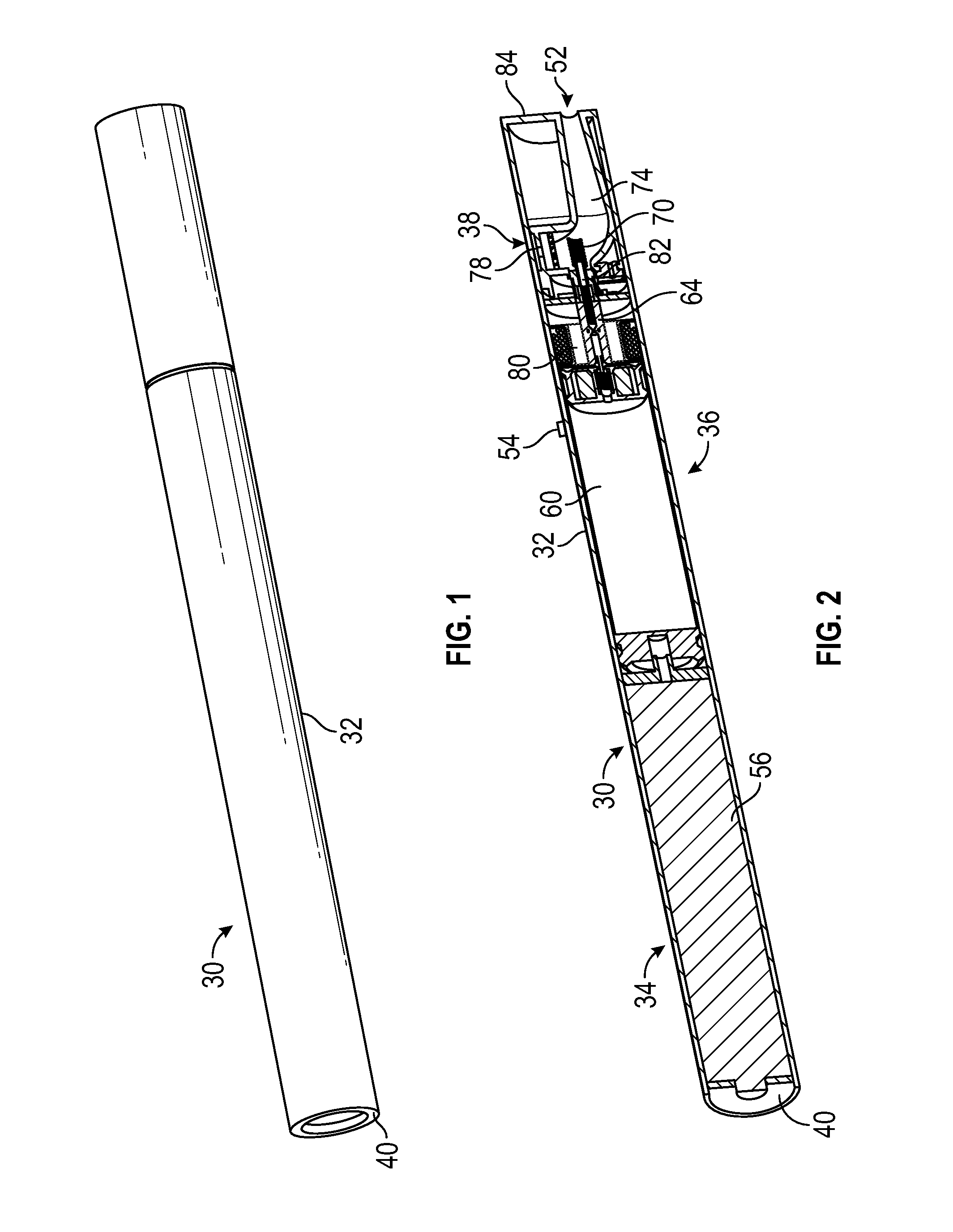
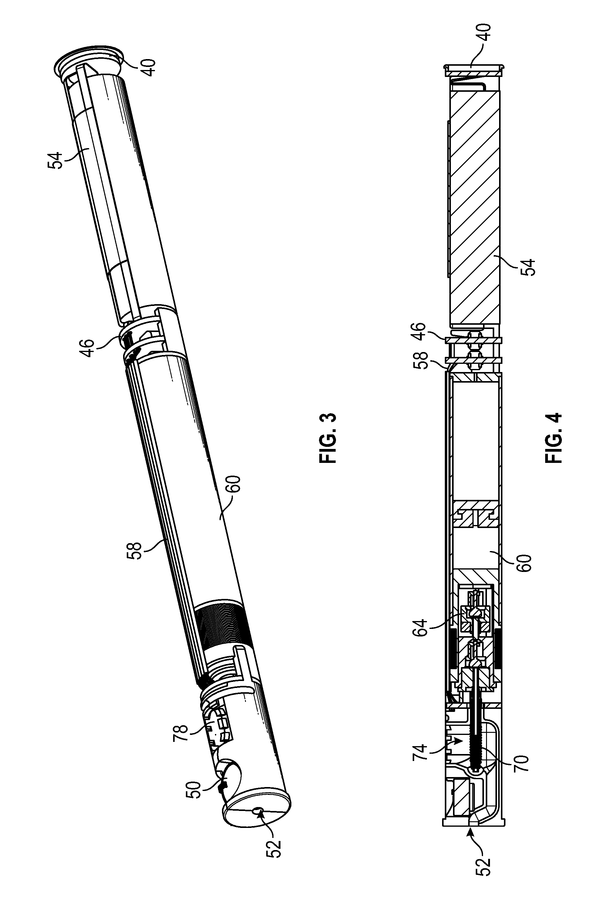
[0037]FIG. 1 illustrates an example of an aerosol generating device 30 that is cylindrical and may have a size and shape similar to a tobacco cigarette, typically about 100 mm long with a 7.5 mm diameter, although lengths may range from 70 to 150 or 180 mm, and diameters from 5 to 20 mm. As shown in FIG. 2, the device 30 has a tubular housing 32 which may be a single piece, or may be divided into two or three separate housing sections, optionally including a battery section 34, a reservoir section 36 and a heater section 38. An LED 40 may be provided at the front end of the device 30 with an outlet 52 at the back end of the device 30.

[0038]In the example shown, a battery 56 and a liquid reservoir 60 are contained within the housing 32. The liquid reservoir 60 contains a liquid, such as a liquid nicotine formulation. A pump 64 is located behind or within the reservoir 60. The pump (e.g., a piston pump or diaphragm pump) can be mechanically or magnetically coupled to a pump motor 80. ...


PUM


Abstract

A device for generating a condensation aerosol includes vaporization chamber having an upstream first inlet and a downstream outlet. A tube supplies liquid to a heater in the vaporization chamber. The liquid is pumped out of the tube and onto the heater, which vaporizes the liquid. Air flows from inlets through the vaporization chamber, and generally perpendicular to the tube. The vaporized liquid is entrained in the air, forming a condensation aerosol having a particle size in a selected range. A second inlet provides a substantially laminar flow of air into the airflow path, wherein the second inlet is downstream of the heater; and the device capable of changing air flow in the vaporization chamber to change the particle size of the condensation aerosol and/or to change the amount of visible vapor emitted from the device.

Description

CROSS-REFERENCE TO RELATED APPLICATION(S)[0001]This application claims priority to U.S. Provisional Patent Application Nos. 62 / 106,679, filed Jan. 22, 2015; 62 / 153,463, filed Apr. 27, 2015; and 62 / 192,377 filed Jul. 9, 2015 and incorporated herein by reference.BACKGROUND OF THE INVENTION[0002]Multiple factors can contribute to tobacco cigarette addiction. Some of the factors include addiction to nicotine or psychological factors including the smell, taste, or social associations of tobacco cigarette smoking. One factor that can drive cigarette addiction is the sensory cues associated with the inhalation and exhalation of smoke itself. Some electronic cigarettes create a large amount of vapor to simulate tobacco cigarette smoke. To avoid vapor deposition in the lung and to preclude exhalation of the vapor, some known devices provide aerosol particles between 0.2 microns and 0.6 microns. Aerosol particles in this size range can be too small to gravitationally settle in the lung during...

Claims


Application Information

Patent Timeline
IPC IPC(8): A24F47/00H05B3/02H05B3/16H05B1/02A24F40/10A24F40/46A24F40/48A24F40/485A24F40/50
CPCA24F47/008H05B3/16H05B3/026H05B1/0244H05B3/46A24F40/46A24F40/10A24F40/50A24F40/48A24F40/485A24B15/167A24F40/42A24F40/51A24F40/53A24F40/95A24F40/20A24F47/00
Inventor WENSLEY, MARTINHUFFORD, MICHAELDLLOYD, PETER
Owner FONTEM VENTURES
Why Eureka
Try Eureka