Method and apparatus for aerial surveillance and targeting

Inactive Publication Date: 2016-08-04
RAFAEL ADVANCED DEFENSE SYSTEMS
View PDF13 Cites 0 Cited by
  • Summary
  • Abstract
  • Description
  • Claims
  • Application Information

AI Technical Summary

Benefits of technology

The invention allows for a device that can capture higher resolution imagery of a target by using a microscope or other imaging technology. This means that researchers and investigators can get more detail about the target, which can be useful for understanding its nature and behavior.

Problems solved by technology

Unfortunately, in many cases the area to be monitored has a complex shape (for example when applied for border control) or few separated areas.
Accordingly, a single LOS with preshaped FOV configuration results in an inefficient area coverage.
Furthermore, FPAs for night vision are much smaller due to technology limitations.
While, in principle, systems of the type described above could provide at least a partial solution to the problem, they in fact generate a new problem that makes them difficult to exploit, inasmuch as the amount of processing and data communication needed to analyze high-resolution images is extremely high, requires extremely high computational powers and slows down processing, resulting in low performance.
On the other hand, it is not possible to avoid using high-resolution images because of the need to clearly identify objects on the ground and relate them to potential threats.
Furthermore, a single airborne targeting system can handle only a single target at a given time.

Method used


Image

  • Method and apparatus for aerial surveillance and targeting
  • Method and apparatus for aerial surveillance and targeting
  • Method and apparatus for aerial surveillance and targeting

Examples


Embodiment Construction

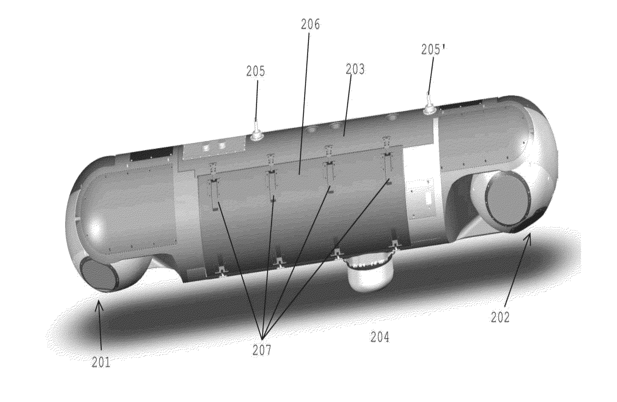
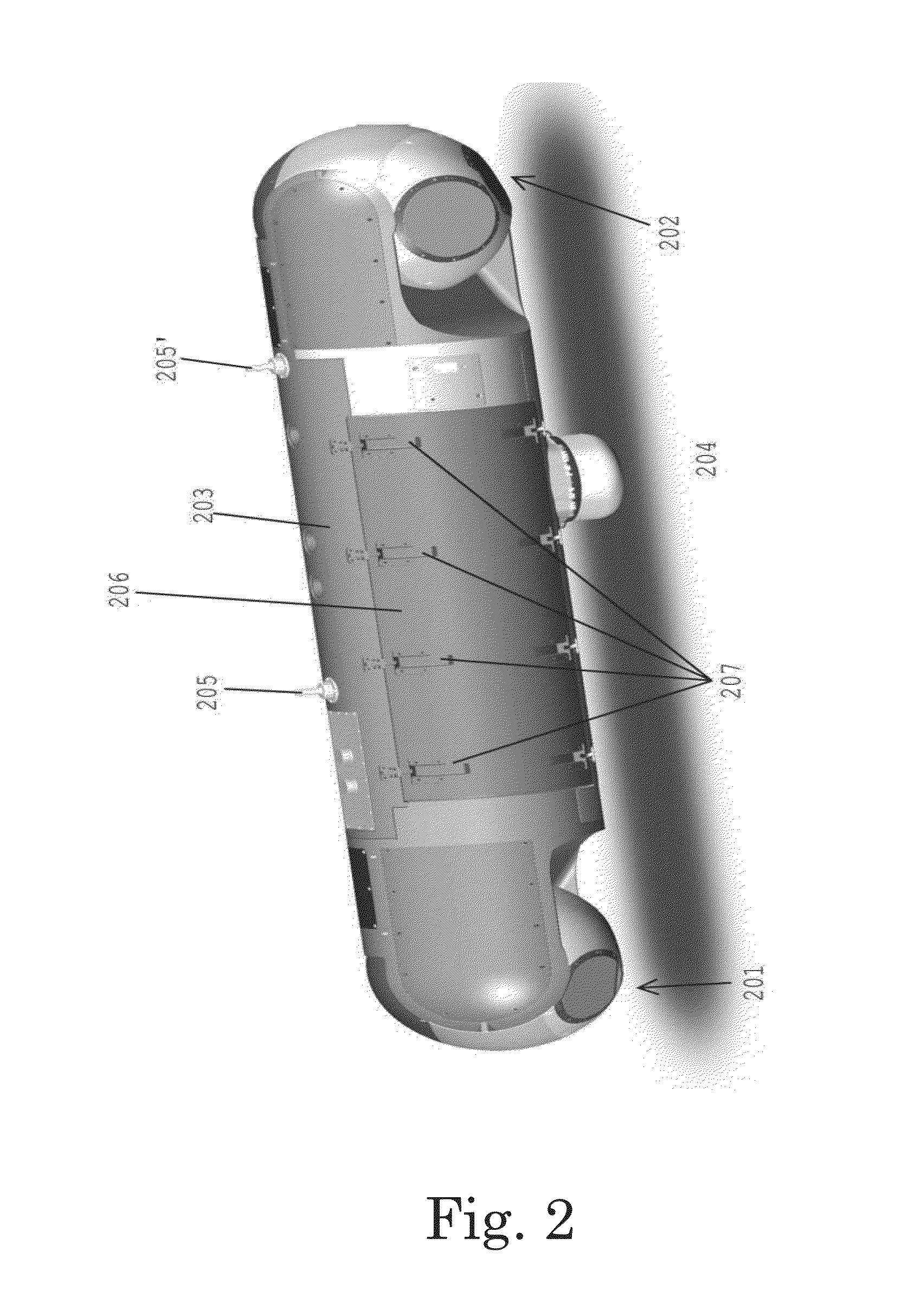
[0044]The invention will now be described with reference to a particular embodiment. Image acquisition can be effective, e.g., using the “step and stare” method described in U.S. Pat. No. 7,126,726, the description of which is incorporated herein by reference. The device according to this embodiment of the invention is pod 200 of FIG. 2. This pod is constructed on the basis of the pod described in U.S. Pat. No. 7,126,726 with reference to its FIG. 1, which is reproduced herein as FIG. 3. While the prior art device has a single optical “head”, mounted in its forward section, the device according to one embodiment of the invention has two gimbal-mounted heads 201 and 202, which are located at two extremities of tubular body 203, and together with it constitute the so-called “pod”. Other elements, such as antenna 204 and connectors 205 and 205′ are known in the art, e.g. from U.S. Pat. No. 7,126,726, and therefore are not described herein in detail, for the sake of brevity. Also a hatc...


PUM


Abstract

An airborne system for performing surveillance of a stationary or moving object on the ground, comprising:two independent image-acquiring devices that are mounted at two extremities of a pod, respectively, a first of said image-acquiring devices is a scanning device which is used for scanning an area of interest and identifying targets therein, and the second of said image acquiring devices is an investigation device which is used for investigating one or more of said identified targets.

Description

FIELD OF THE INVENTION[0001]The invention relates to the field of aerial surveillance and targeting. More particularly, the invention relates to a system and apparatus suitable for performing surveillance over wide areas, when large amounts of image data needs to be analyzed, and for designating selected targets.BACKGROUND OF THE INVENTION[0002]Arial surveillance has become of critical importance for security purposes, to locate, identify and understand security threats, and to trace those security threats back to their origin. Many efforts and money have gone into seeking solutions that would permit to monitor large areas for extended periods of time, such as in the “ARGUS-IS” project.[0003]The ARGUS-IS, or the Autonomous Real-Time Ground Ubiquitous Surveillance Imaging System, is a Defense Advanced Research Projects Agency (DARPA) project contracted to BAE Systems. According to DARPA, the mission of the Autonomous Real-time Ground Ubiquitous Surveillance-Imaging System (ARGUS-IS) ...

Claims


Application Information

Patent Timeline
IPC IPC(8): G06K9/00G06T7/20B64D47/00H04N7/18
CPCG06K9/00771H04N7/181G06K9/0063G06T2207/30232B64D47/00G06T2207/10032G06T7/20H04N7/185B64D47/08G06V20/52
Inventor GREENFELD, ISRAELYAVIN, ZVI
Owner RAFAEL ADVANCED DEFENSE SYSTEMS
Why Eureka
Try Eureka