Snap Hook

a technology of snap hooks and hooks, which is applied in the direction of hooks, fastening means, mechanical devices, etc., can solve the problems of difficult inserting of locking members, etc., and achieve the effect of reliable and convenient snap hooks

Inactive Publication Date: 2016-08-11
HUANG CHIN SHUN
View PDF27 Cites 14 Cited by
  • Summary
  • Abstract
  • Description
  • Claims
  • Application Information

AI Technical Summary

Benefits of technology

[0009]It is the primary objective of the present invention to provide a reliable and convenient snap hook.

Problems solved by technology

However, it is difficult to insert the locking member 200 in the gate 400 since the gate 400 is small.

Method used


Image

  • Snap Hook
  • Snap Hook
  • Snap Hook

Examples


Embodiment Construction

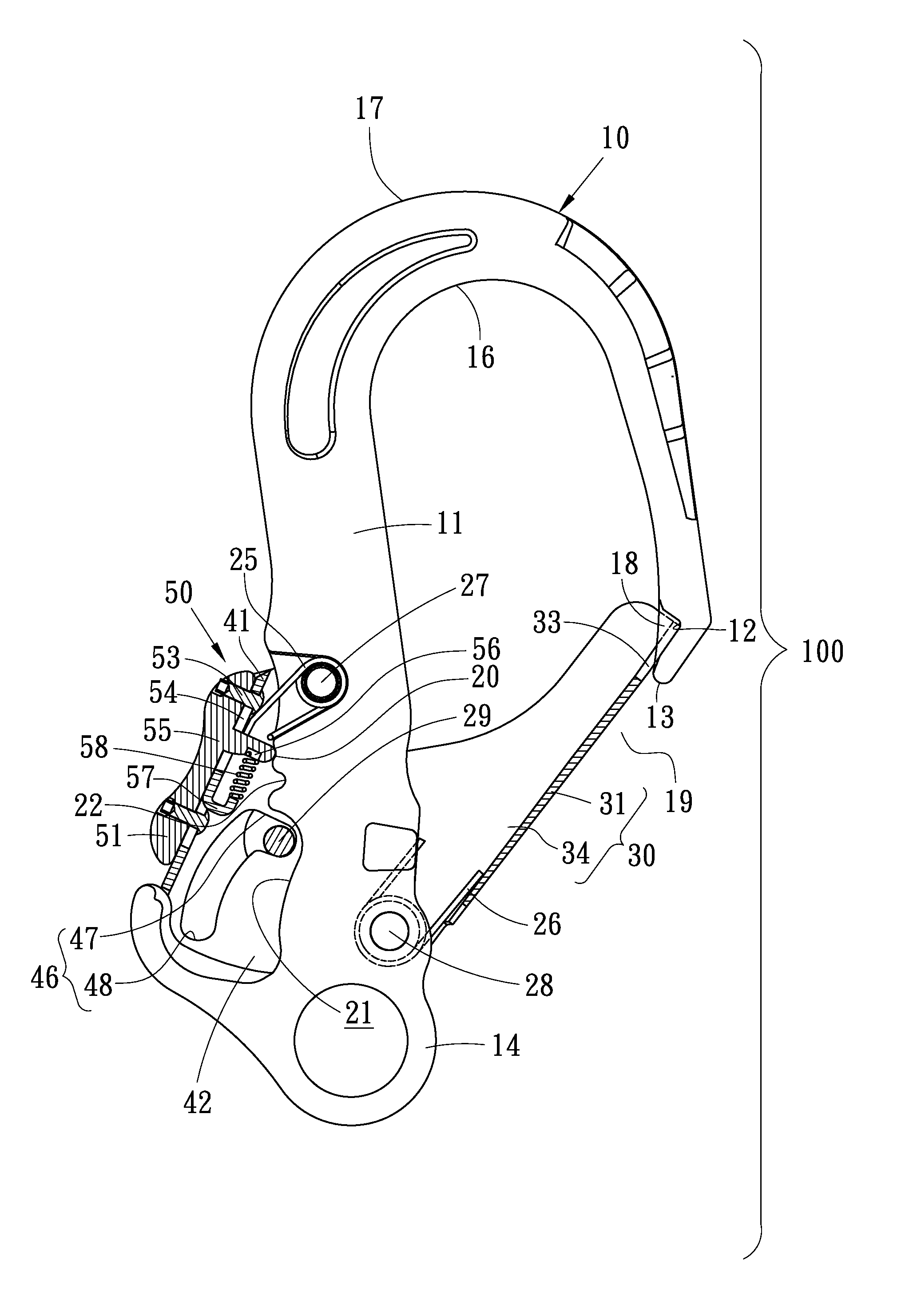
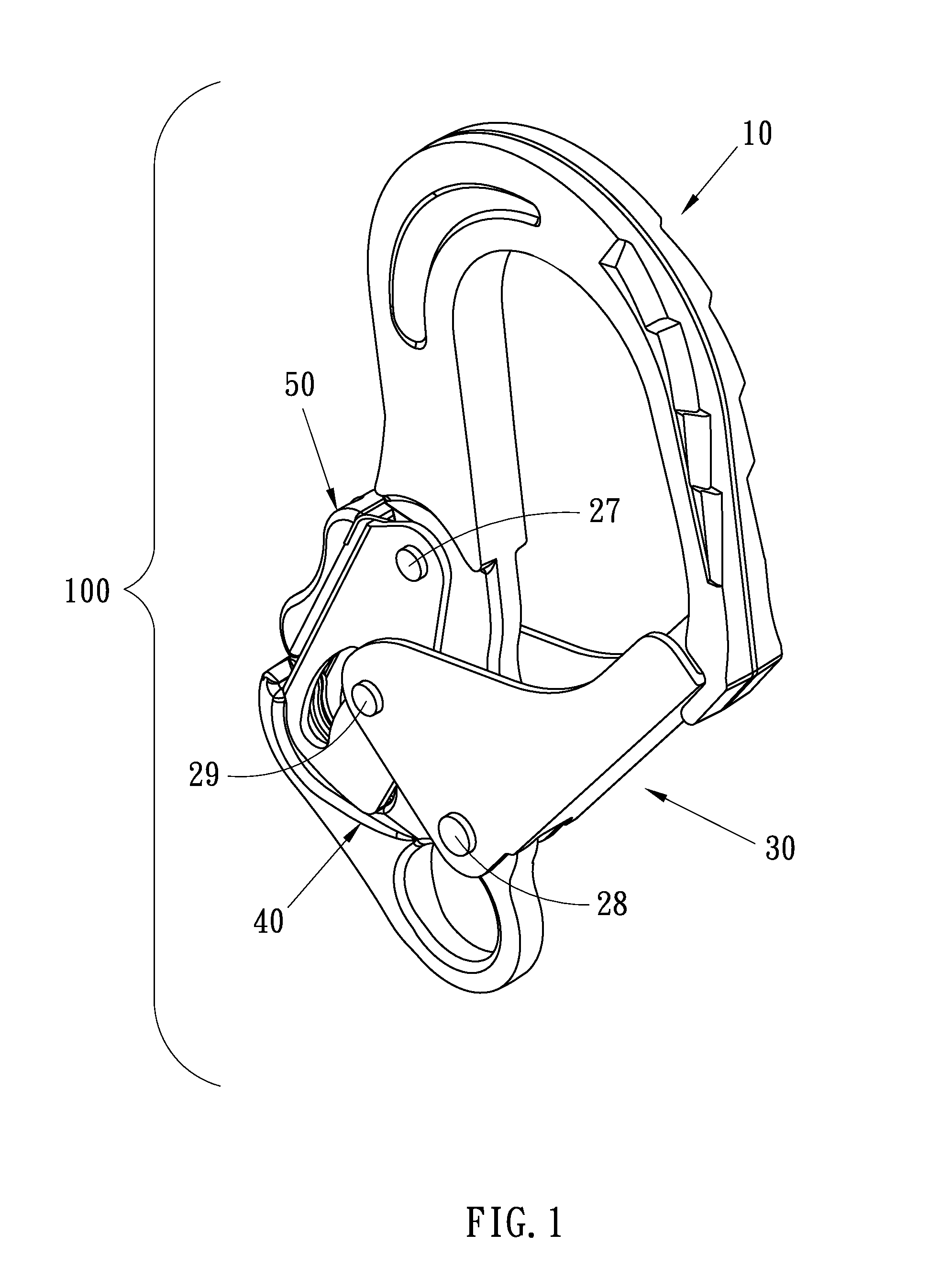
[0021]Referring to FIG. 1, a snap hook 100 includes an arched body 10, a gate 30, a lock 40 and a security device 50 according to the preferred embodiment of the present invention. The gate 30 is used to close the arched body 10. The lock 40 is used to lock the gate 30. The security device 50 is used to restrain the lock 40.

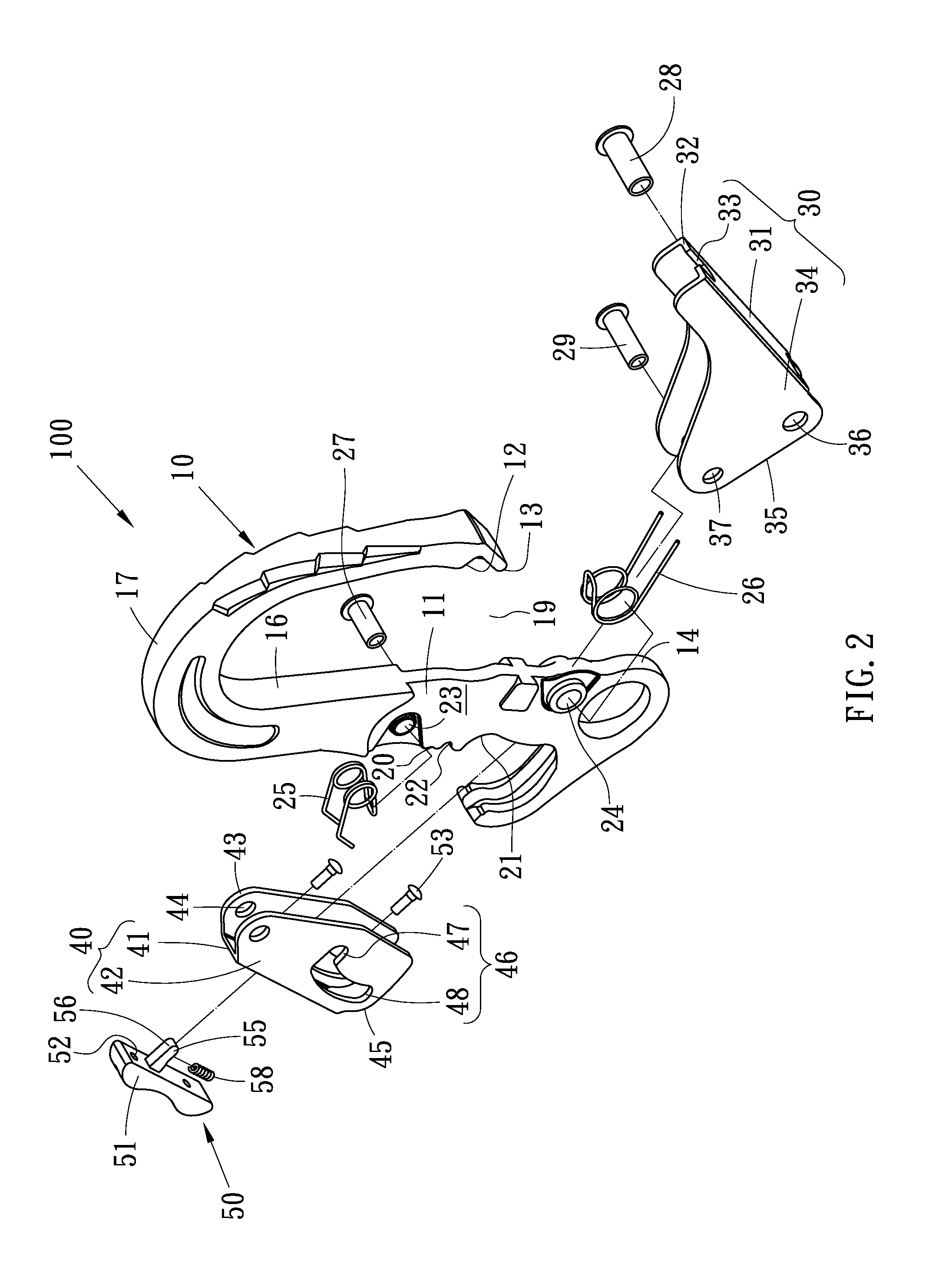
[0022]Referring to FIGS. 2 and 3, the arched body 10 includes a first end 13, a second end (not numbered), a middle section 11 between the first end 13 and the second end, and an opening 19 between the first end 13 and the middle section 11. The arched body 10 further includes an aperture 14 near the second end. The arched body 10 further includes an internal edge 16 directed to the opening 19 and an external edge 17 opposite to the internal edge 16. The arched body 10 further includes, in the vicinity of the first end 13, two recesses 12 in the internal edge 16 and a fin 18 at the internal edge 16. The recesses 12 are separated from each other by the fin 18.

[002...


PUM


Abstract

A snap hook includes a body, a gate, a lock and a security device. The body includes an opening and a cutout. The gate is pivotally connected to the body between a closing position to close the opening and an opening position to open the opening. The lock is pivotally connected to the body between a locking position to avoid pivoting of the gate into the opening position and a releasing position to allow the gate to pivot into the opening position. The security device includes a switch movably located on the lock between two positions and a tongue extending from the switch. In the first position of the switch, the tongue abuts the body to avoid pivoting of the lock into the releasing position. In the second position of the switch, the tongue is allowed to enter the cutout to allow the lock to pivot into the releasing position.

Description

BACKGROUND OF INVENTION[0001]1. Field of Invention[0002]The present invention relates to a snap hook and, more particularly, to a reliable snap hook.[0003]2. Related Prior Art[0004]As disclosed in U.S. Pat. No. 5,896,630, a snap hook 1 includes a body, a gate keeper 8 for closing an opening 7 made by the body, a first locking means for locking the gate keeper 8, and a second locking means 17 for locking the first locking means. The body includes a shank 2 and an arched portion 3 formed at an end of the shank 2. The gate keeper 8 is formed with two locking tabs 15. The first locking means includes a locking lever 11 pivotally connected to the shank 2. The locking lever 11 includes two locking arms 14 and a slot 21. The second locking means 17 includes a slide plate 18 and a pin 20. The pin 20 is inserted in the slot 21. The slide plate 18 includes two tabs 23 on a side. An internal spring 13 is place against another side of the slide plate 18 to force the tabs 23 towards the locking ...

Claims


Application Information

Patent Timeline
Patent Type & Authority Applications(United States)
IPC IPC(8): F16B45/02
CPCF16B45/02F16B45/023F16B45/026F16B45/028
Inventor HUANG, CHIN-SHUN
Owner HUANG CHIN SHUN
Why Eureka
Try Eureka