Pneumatic insole

a pneumatic and insole technology, applied in the field of pneumatic insoles, can solve the problems of non-elastic airbag inflated, non-elastic airbag inflated and non-elastic, and loss of cushioning ability

Active Publication Date: 2017-12-12
CHANG CHI YUAN
View PDF17 Cites 11 Cited by
  • Summary
  • Abstract
  • Description
  • Claims
  • Application Information

AI Technical Summary

Benefits of technology

[0006]It is the primary objective of the present invention to provide a convenient and reliable pneumatic insole.

Problems solved by technology

However, the pneumatic insole assembly does not include any built-in pump so that the airbags are inflated by an external device such as a pump, and this is inconvenient.
Moreover, the insole does not include any valve for releasing air when the airbags are excessively inflated so that the extent to which the airbags is inflated is not adjustable, and this is not desirable.
However, the heel of the foot could press the pump to inflate the airbag by accident.
These materials exhibit capillarity that allows air to leak from the airbag after two or three months of use so that the airbag is inflated and non-elastic and loses the ability to cushion.
However, this attempt is ineffective.
This attempt is ineffective.
Moreover, it increases the weight of airbag.

Method used


Image

  • Pneumatic insole
  • Pneumatic insole
  • Pneumatic insole

Examples


first embodiment

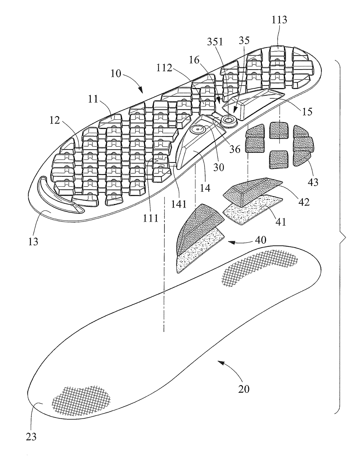
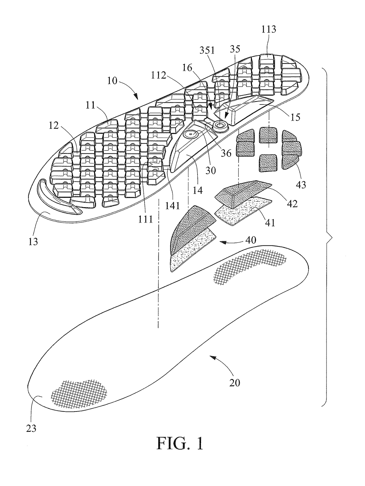
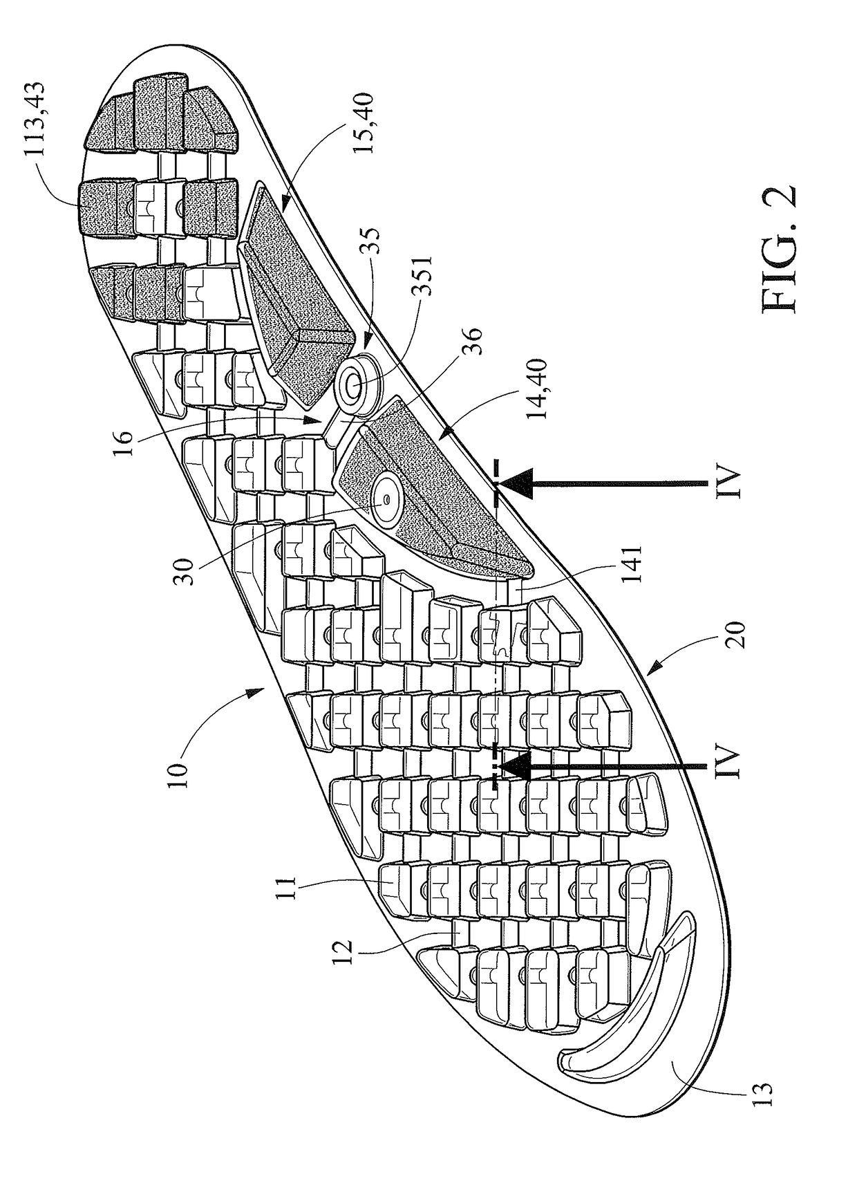
[0029]Referring to FIGS. 1 through 3, a pneumatic insole includes an upper layer 10 and a lower layer 20 according to the present invention. By thermoplastic molding, the upper layer 10 is provided with airbags 11 and channels 12 via which the airbags 11 are in communication of air with one another. The upper layer 10 includes a margin 13 that is connected to a margin 23 of the lower layer 20 by melting technology so that there is air-tightness between the upper and lower layers 10 and 20. The margins 13 and 23 of the upper and lower layers 10 and 20 of the pneumatic insole can be cut or trimmed to fit a particular size and shape of a shoe, boot or sneaker in which the pneumatic insole is to be used.

[0030]The pneumatic insole includes two arch-related chambers 14 and 15 in an arch-related portion. The arch-related chamber 14 includes a push-type inlet valve 30. The arch-related chamber 14 is in communication with one of the airbags 11 (further referred to by “the leading airbag 111”...

second embodiment

[0035]Referring to FIG. 6, there is a pneumatic insole according to the present invention. The second embodiment is identical to the first embodiment except for two things. Firstly, there is a connective airbag 17 via which the arch-related chamber 14 is communication with the arch-related chamber 15. Secondly, the recessed portion 16, which is located between the arch-related chamber 14 and the arch-related chamber 15, is reduced in size. The connective airbag 17 extends over the outlet channel 36. That is, the connective airbag 17 and the outlet channel 36 do not interfere with each other.

[0036]Before the pneumatic insole is used, all of the airbags 11, which includes the airbags 111, 112 and 113, must be inflated. The arch-related chamber 14 is pressed to actuate the push-type inlet valve 30 to pump air into the airbag 111 from the exterior via the arch-related chamber 14, inlet channel 141 and the check valve 31. Since all of the airbags 11 are interconnected by the channels 12,...


PUM

PropertyMeasurementUnit
elasticityaaaaaaaaaa
coloraaaaaaaaaa
thicknessaaaaaaaaaa

Abstract

A pneumatic insole includes airbags, channels, two arch-related chambers, a push-type inlet valve, an inlet channel, a check valve, a recessed portion, a push-type adjustment valve, and an outlet channel. The channels interconnect the airbags. The push-type inlet valve is located in the first arch-related chamber. The inlet channel connects the first arch-related chamber to a leading one of the airbags. The check valve is arranged between the inlet channel and the inlet airbag. The recessed portion is located between the arch-related chambers. The push-type adjustment valve is located in the recessed portion and formed with an upper face that extends lower than that of the first and second arch-related chambers. The outlet channel connects the push-type adjustment valve to another one of the airbags.

Description

BACKGROUND OF INVENTION1. Field of Invention[0001]The present invention relates to insoles and, more particularly, to a pneumatic insole.2. Related Prior Art[0002]Many pneumatic insoles have been devised. For example, Taiwanese Patent No. M380726 discloses a pneumatic insole assembly that includes airbags provided on an insole. Each of the airbags includes a valve. Air is pumped into the airbags via the valves. However, the pneumatic insole assembly does not include any built-in pump so that the airbags are inflated by an external device such as a pump, and this is inconvenient. Moreover, the insole does not include any valve for releasing air when the airbags are excessively inflated so that the extent to which the airbags is inflated is not adjustable, and this is not desirable.[0003]Taiwanese Patent No. M503777 discloses an insole assembly that includes an airbag and a pump provided on an insole. The airbag and the pump are located on a portion of the insole corresponding to an a...

Claims


Application Information

Patent Timeline
Patent Type & Authority Patents(United States)
IPC IPC(8): A43B17/03A43B7/14
CPCA43B17/035A43B7/141A43B7/1445A43B17/03A43B7/142A43B13/203A43B13/206A43B17/14
Inventor CHANG, CHI-YUAN
Owner CHANG CHI YUAN
Why Eureka
Try Eureka