Spinal plate selection and positioning system

a positioning system and spine plate technology, applied in the field of spine plate selection and positioning system, medical implants and instruments, can solve the problems of inability to ensure, difficulty in realizing proper alignment and positioning of the interbody cage, and inability to achieve the effect of correct positioning and alignmen

Inactive Publication Date: 2016-08-18
RETROSPINE
View PDF0 Cites 26 Cited by
  • Summary
  • Abstract
  • Description
  • Claims
  • Application Information

AI Technical Summary

Problems solved by technology

In practice, however, proper alignment and positioning of the interbody cage may be difficult to accomplish due to (i) narrow wounds which obscure surgical landmarks; (ii) blood or other tissue may obscure landmarks; (iii) the interbody plate itself may obscure landmarks; (iv) drill guides that are used to drill pilot holes may further obscure landmarks; and (v) the interbody plate may move prior to being secured without the surgeon being aware.
This technique, however, has limitations.
O...

Method used


Image

  • Spinal plate selection and positioning system
  • Spinal plate selection and positioning system
  • Spinal plate selection and positioning system

Examples


Embodiment Construction

[0029]For the purposes of promoting an understanding of the principles in accordance with the disclosure, reference will now be made to the embodiments illustrated in the drawings and specific language will be used to describe the same. It will nevertheless be understood that no limitation of the scope of the disclosure is thereby intended. Any alterations and further modifications of the inventive features illustrated herein, and any additional applications of the principles of the disclosure as illustrated herein, which would normally occur to one skilled in the relevant art and having possession of this disclosure, are to be considered within the scope of the disclosure claimed.

[0030]In describing and claiming the present disclosure, the following terminology will be used in accordance with the definitions set out below. It must be noted that, as used in this specification and the appended claims, the singular forms “a,”“an,” and “the” include plural referents unless the context ...


PUM


Abstract

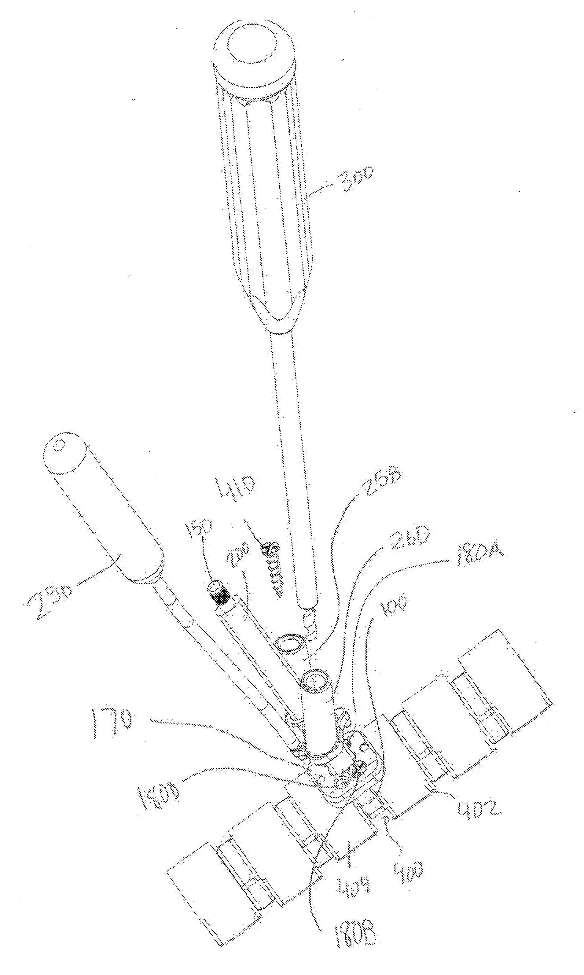
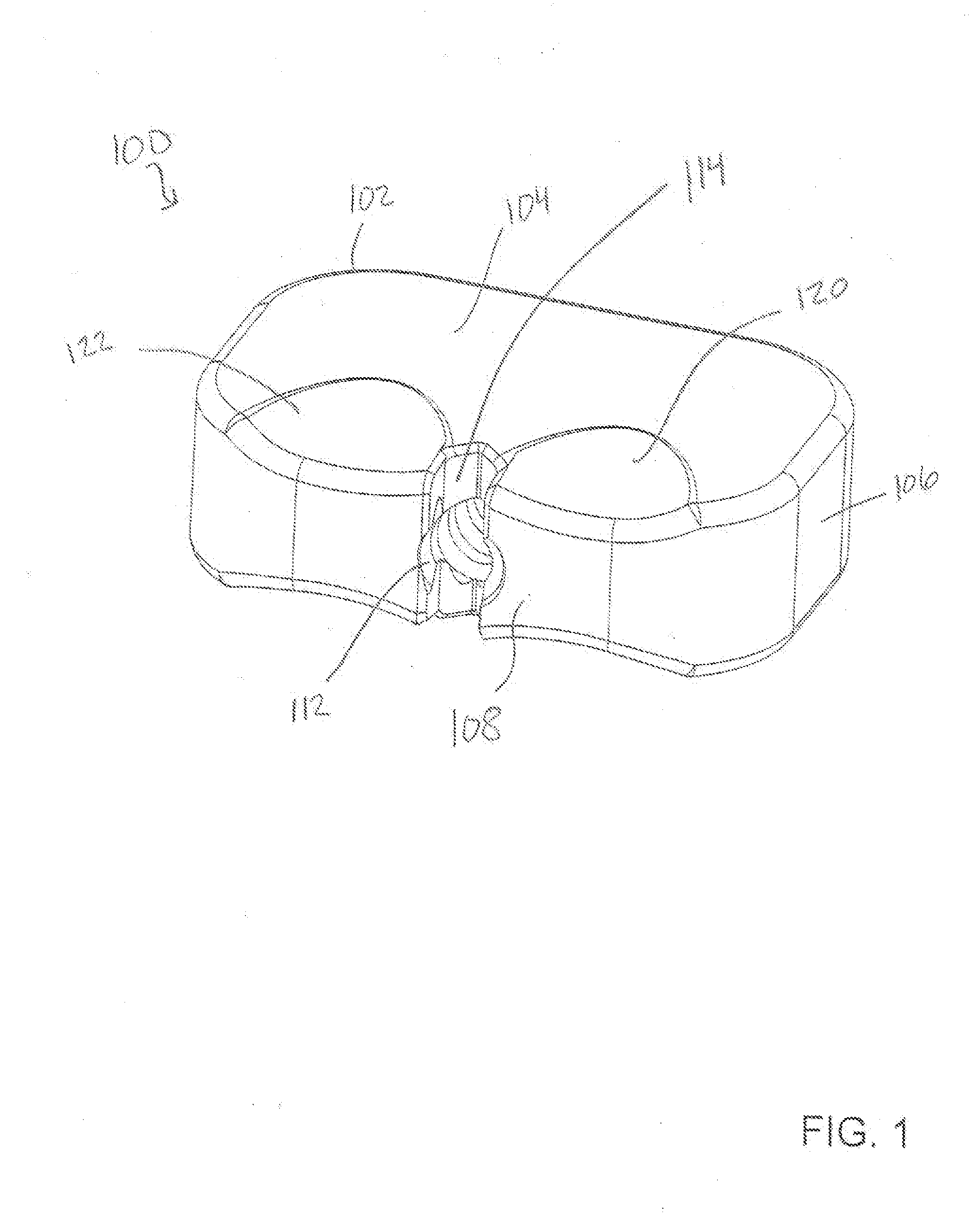
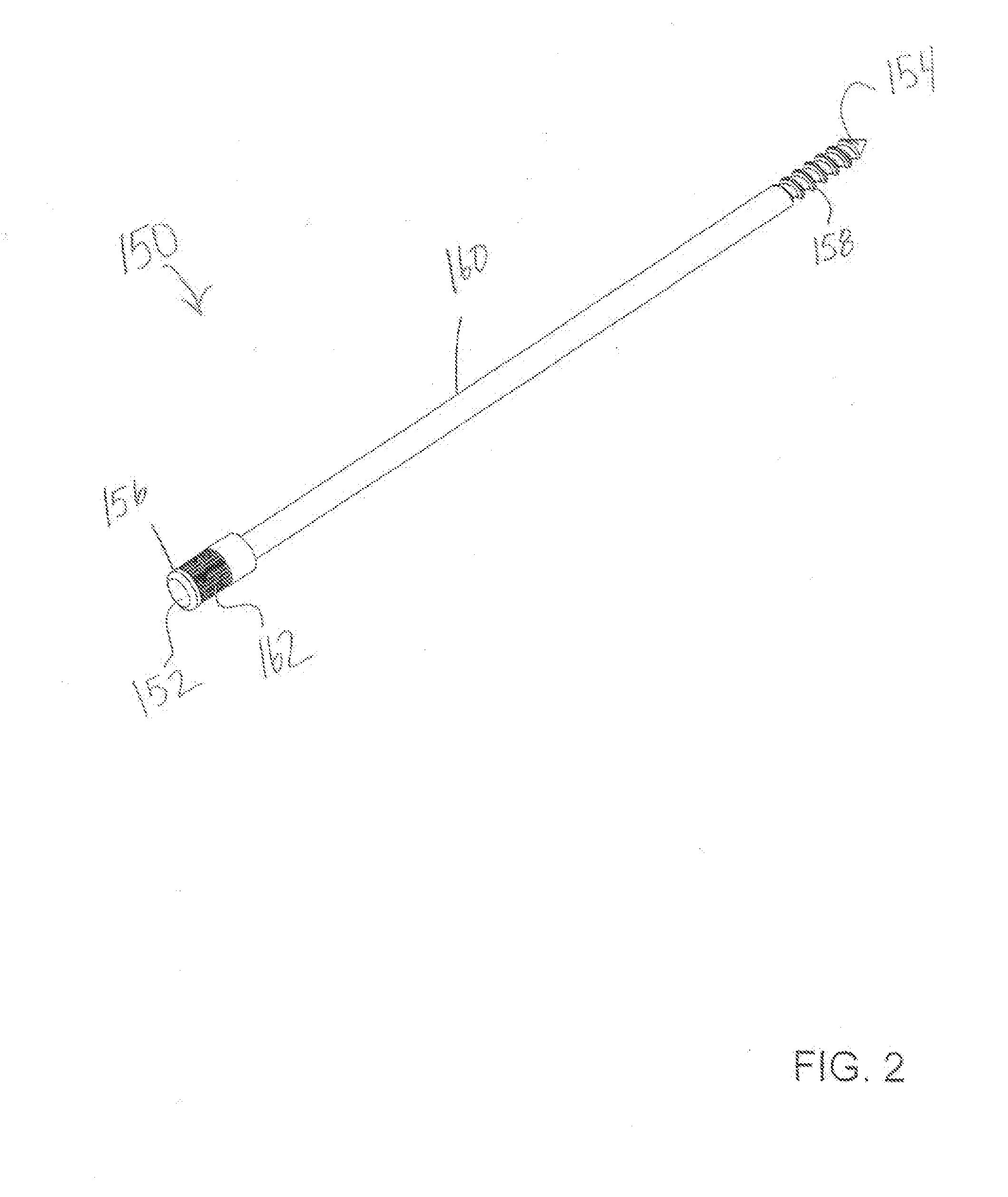
A spinal plate selection and positioning system is provided for use in a spinal fusion procedure. The system may comprise an elongated guide member that is removably securable to an interbody cage by a holding rod. An interbody plate may be aligned and positioned above the interbody cage installed in a disc space. A drill guide may also be aligned and positioned above the interbody plate. The drill guide may be utilized to drill pilot holes in the vertebrae defining the disc space. Fasteners to secure the interbody plate may also by installed using the drill guide. The use of the guide member ensures that the interbody plate is properly aligned and positioned with respect to the interbody cage.

Description

CROSS-REFERENCE TO RELATED APPLICATIONS[0001]This application is a continuation of U.S. patent application Ser. No. 14 / 157,412, filed Jan. 16, 2014, which claims the benefit of U.S. Provisional Application No. 61 / 753,420, filed Jan. 16, 2013, entitled “SPINAL PLATE SELECTION AND POSITIONING SYSTEM,” which is hereby incorporated by reference herein in its entirety, including but not limited to those portions that specifically appear hereinafter, the incorporation by reference being made with the following exception: In the event that any portion of the above-referenced applications is inconsistent with this application, this application supercedes said above-referenced applications.STATEMENT REGARDING FEDERALLY SPONSORED RESEARCH OR DEVELOPMENT[0002]Not Applicable.BACKGROUND[0003]1. The Field of the Present Disclosure[0004]The present disclosure relates generally to medical devices, and more particularly, but not necessarily entirely, to medical implants and instrumentation utilized ...

Claims


Application Information

Patent Timeline
IPC IPC(8): A61B17/70A61F2/44
CPCA61B17/1728A61B17/1757A61B17/7059A61B17/808A61F2/4455A61F2002/4629A61F2/4684A61F2002/3082A61F2002/30836A61F2002/4475A61F2002/4627A61F2/4611A61F2002/30593
Inventor SEEX, KEVIN
Owner RETROSPINE
Why Eureka
Try Eureka