Cannulated drill bit with radially offset cutting edge

a drill bit and cutting edge technology, applied in the field of cannulated drill bits with radially offset cutting edges, can solve the problems of interference between the medial femoral condyle and the drill bit periphery, and the radius of the drill bit where the guidewire may be placed,

Active Publication Date: 2009-01-22
LINVATEC
View PDF6 Cites 42 Cited by
  • Summary
  • Abstract
  • Description
  • Claims
  • Application Information

AI Technical Summary

Benefits of technology

[0014](5) In this way, the cutting device may engage the distal femur at a location much closer to the center of the femoral notch by a matter of several millimeters than is the case with prior a

Problems solved by technology

When this technique is employed, it is advantageous to place the guidewire deliberately close to the medial femoral condyle, however, using prior art drill bits, the closest the guidewire may be placed is limited to the drill bit radius plus the appropri

Method used


Image

  • Cannulated drill bit with radially offset cutting edge
  • Cannulated drill bit with radially offset cutting edge
  • Cannulated drill bit with radially offset cutting edge

Examples


Embodiment Construction

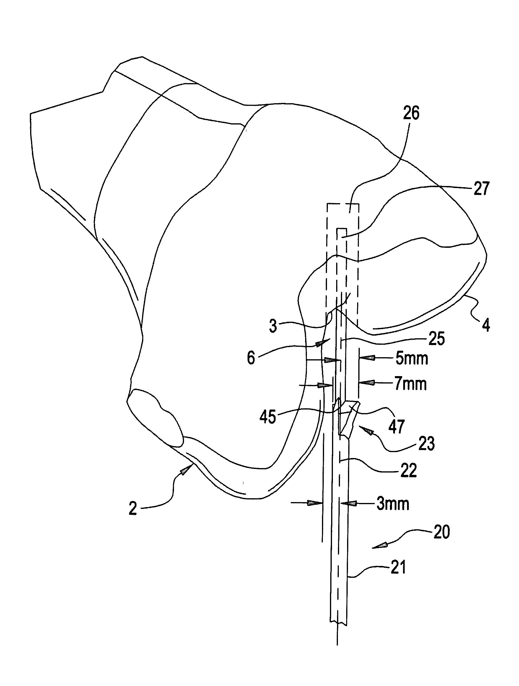
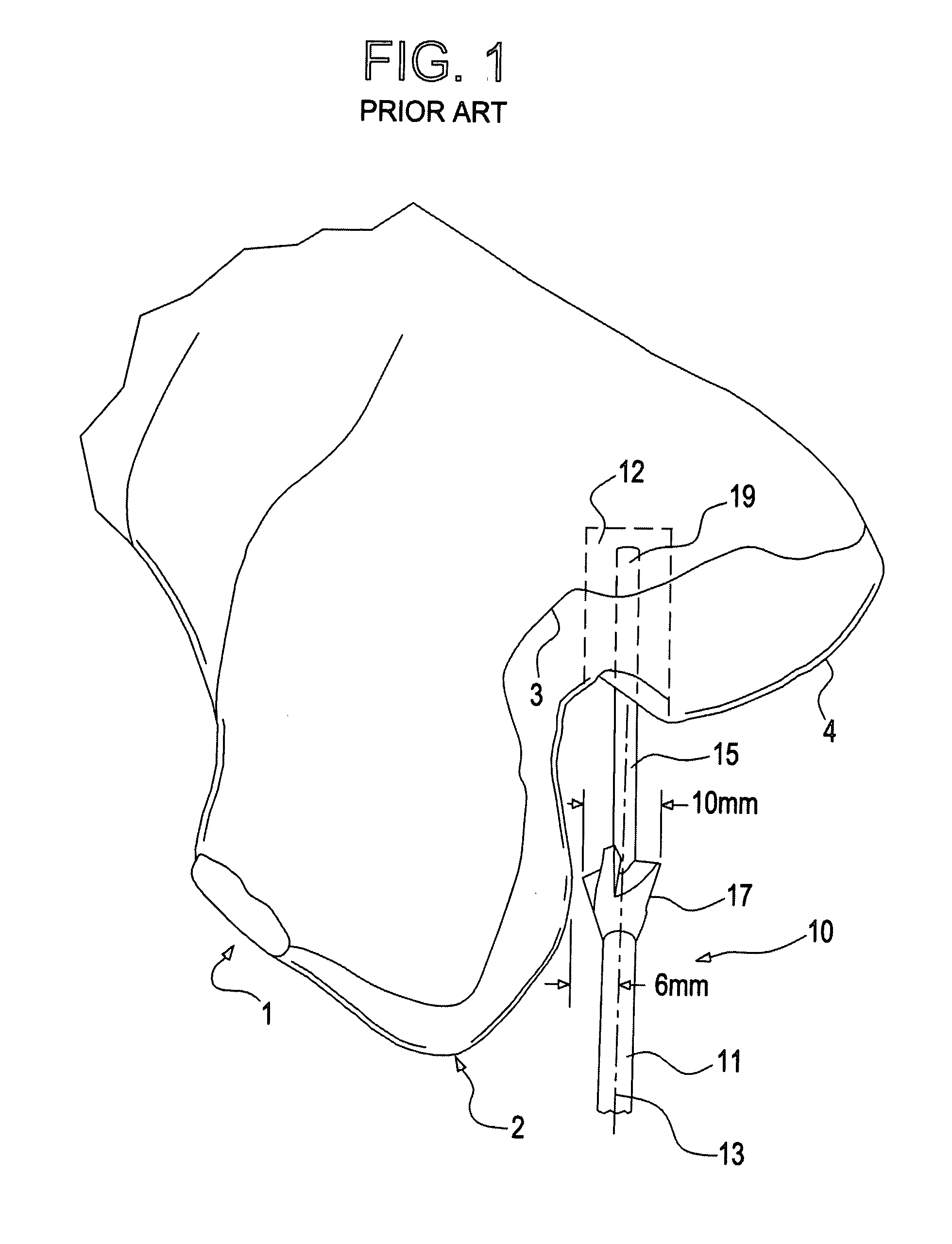
[0028]Reference is first made to FIG. 1 which shows a distal femur 1 having a medial femoral condyle 2, an intercondylar notch 3, and a lateral femoral condyle 4.

[0029]With further reference to FIG. 1, a prior art drill bit 10 includes a proximal end 11 having an axis of rotation 13, a distal cutting member 17, and a guide wire 15 extending through an axial passageway formed through the bit 10. The cutting member 17 extends completely about the periphery of the bit 10. As seen in FIG. 1, the diameter of the cutting member 17 may be, for example, 10 mm and, for this size drill bit, the cutting member 17 passes about 1 mm from the medial femoral condyle when preparing to drill a graft tunnel hole 12 shown in phantom. The guide wire 15 has a distal cutting surface (not shown) that permits cutting a pilot hole 19 shown in phantom in FIG. 1, whereupon the distal cutting member 17, guided by the guide wire 15, enlarges the pilot hole 19 to form the graft tunnel hole 12. As explained above...


PUM


Abstract

A drill bit has a cylindrical proximal end coupled to a driving device with a central axis of rotation about which the proximal end rotates. A distal portion of the drill bit is a cutting device attached to the proximal end in such a way that it extends outside the periphery of the proximal end for a distance less than the entirety of the circumference of the proximal end. A guide wire extends through a passageway in the bit and is provided to create a pilot hole before the distal portion enlarges that hole. With this configuration of the cutting device, it is possible to position the cutting device in the distal portion in a direction facing away from the medial femoral condyle so that the proximal end of the drill bit can slide past the medial femoral condyle, with its axis of rotation much closer to that condyle than would be the case in prior art drill bits.

Description

BACKGROUND OF THE INVENTION[0001]The present invention relates to a cannulated drill bit with radially offset cutting edge. In the performance of orthopedic surgery such as, for example, a surgery known as double bundle ACL reconstruction, one procedure required to be performed is that of drilling a graft tunnel hole for the posterior lateral graft bundle in the lateral condyle of the femur. In order to perform this drilling procedure to the greatest advantage, it is best to place the tunnel sufficiently posterior to provide a proper location for the graft.[0002]In so drilling the tunnel, it has been found that it is most advantageous to pass the drill bit as close as possible to the medial femoral condyle so that the hole is drilled in the most proper location.[0003]Currently, drill bits that are employed have an axis of rotation that is the same for both the proximal and distal ends thereof. The proximal end of the drill bit is coupled to a drill that facilitates rotation of the p...

Claims


Application Information

Patent Timeline
IPC IPC(8): A61B17/56
CPCA61B17/1615A61B17/1675A61B17/1637
Inventor LOMBARDO, GIUSEPPE
Owner LINVATEC
Why Eureka
Try Eureka