
Methods of drilling through-holes in homogenous and non-homogeneous substrates

a technology of homogenous and non-homogeneous substrates, applied in the direction of manufacturing tools, welding/soldering/cutting articles, semiconductor/solid-state device details, etc., can solve the problems of inability to mechanically drill through the hole, non-homogeneous substrates, and imperfect laser drilling methods, etc., to achieve minimal thermal damage, improve performance, and reduce the effect of mechanical drilling

Inactive Publication Date: 2005-10-20
ELECTRO SCI IND INC
View PDF12 Cites 42 Cited by
  • Summary
  • Abstract
  • Description
  • Claims
  • Application Information

AI Technical Summary

Benefits of technology

[0011] An object of the present invention is, therefore, to provide ah efficient and economical method of forming a through-hole in a non-homogeneous substrate using a high-power laser to effect controlled target material and thermal energy removal. The resulting through-hole exhibits a smooth wall and minimal thermal damage. The overall result is a method of performing laser operations that offers improved performance in terms of processing quality, reproducibility of the technological result, ability to drill high aspect ratio through-holes, and effectiveness at low additional cost.
[0013] The pilot hole forms a channel through which thermal energy produced during laser drilling may diffuse into the environment, thereby reducing the amount of thermal energy diffusing into the surrounding target material matrix and the degree of thermal damage to the heat affected zone of the target material matrix. Careful selection of the pilot hole diameter and the drilling parameters provides significant reduction in the amount of thermal damage to the heat affected zone surrounding the through-hole during its formation and enhances the wall quality of the drilled through-hole.
[0014] The pilot hole also forms a channel through which drilled target material may be removed, thereby increasing overall through-hole throughput. Because a portion of the total target material that must be removed as part of the through-hole formation process is ablated and removed during formation of the pilot hole, the thermal energy required to remove the remaining portion of target material is reduced. When less thermal energy is needed to form the remaining portion of the through-hole, less thermal damage to the surrounding target material matrix results.
[0017] The method of the present invention facilitates the formation of high-aspect ratio through-holes because the depth of the through-hole can be increased without incurring increased through-hole wall thermal damage. Additionally, the method enables an increase in the material removal rate and thereby reduces manufacturing costs and increases overall via-per-second throughput. The method of the present invention also avoids or minimizes the undesirable formation of grooved structures on the side walls of the through-holes, slag deposits adhering to the bottom edge of the cut, and thermal damage to the surrounding target material matrix. Thus the method of the present invention promotes through-hole quality and throughput.

Problems solved by technology

Through-holes are typically drilled mechanically; however, the growing need for small diameter (e.g., less than 150 microns) through-holes has made mechanical drilling of them impracticable.
Although laser drilling facilitates the formation of small-diameter through-holes, through-hole laser drilling remains an imperfect method plagued by various problems.
One problem with laser-drilling through-holes in nonhomogeneous substrates is that they typically exhibit poor wall quality.
As the high-power laser drills deeper into the target material, more of the thermal energy added remains in the hole than can escape through the top opening, resulting in a significant amount of thermal energy diffusing through the hole wall into the target material matrix.
This diffusion causes significant structural damage to the target material located within the heat affected zone.
Further, the inability to efficiently remove drilled target material through the top opening of the through-hole results in the formation of through-holes having undesirable fiber protrusions and / or resin etchback.
A second problem with laser-drilling through-holes is the formation of grooves on the through-hole walls, which result from interaction between the laser beam and the target material.
A third problem with laser-drilling through-holes is that a portion of the drilled target material can partly block subsequent laser pulses or form a plasma plume.
For example, target material debris remaining in the hole during laser drilling often ignites and etches out into the heat affected zone.
This occurrence typically results in undesirable resin etchback.
Additionally, superheated debris can change the nature of the ablation process from predominantly ablative to less ablative and more thermal, thereby creating a saturation depth that unfavorably imposes a practical limit on the power density and repetition rate of the high-power laser.
A fourth problem with laser-drilling through-holes occurs when forming through-holes in highly heterogeneous materials, such as FR4 cloths, which are organic polymer resin-impregnated glass cloths sandwiched between electrically and thermally conductive metal layers.
Because the laser ablation characteristics, such as melting and vaporization temperatures, differ for each individual layer, laser processing through-holes is very difficult.
Silicon dioxide (a commonly used woven glass reinforcement) has a melting temperature of about 1,970 Kelvin (K) and a vaporization temperature of about 2,503 K. In contrast, organic resins (i.e., epoxies) vaporize between about 500 K and about 700 K. The disparity in vaporization temperatures makes it difficult to laser-ablate the glass component without ablating the resin surrounding individual glass fibers or in regions directly adjacent to fiber bundles.
However, the degree of improvement that can be made using this method is relatively minimal because optimization of one parameter is often detrimental to a separate aspect of through-hole formation.
Although high-power laser drilling is an integral part of semiconductor micromachining technology, no economically efficient laser drilling method has been found to drill through-holes having smooth walls with a reduced incidence of cut-surface groove formation, fiber protrusion, or fiber etchback.

Method used


Image

  • Methods of drilling through-holes in homogenous and non-homogeneous substrates
  • Methods of drilling through-holes in homogenous and non-homogeneous substrates
  • Methods of drilling through-holes in homogenous and non-homogeneous substrates

Examples


Embodiment Construction

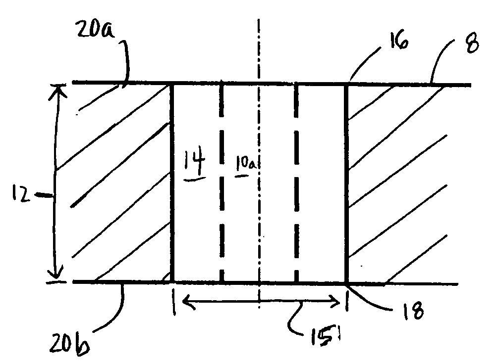
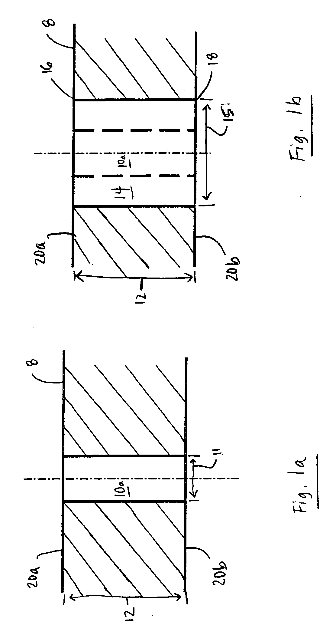
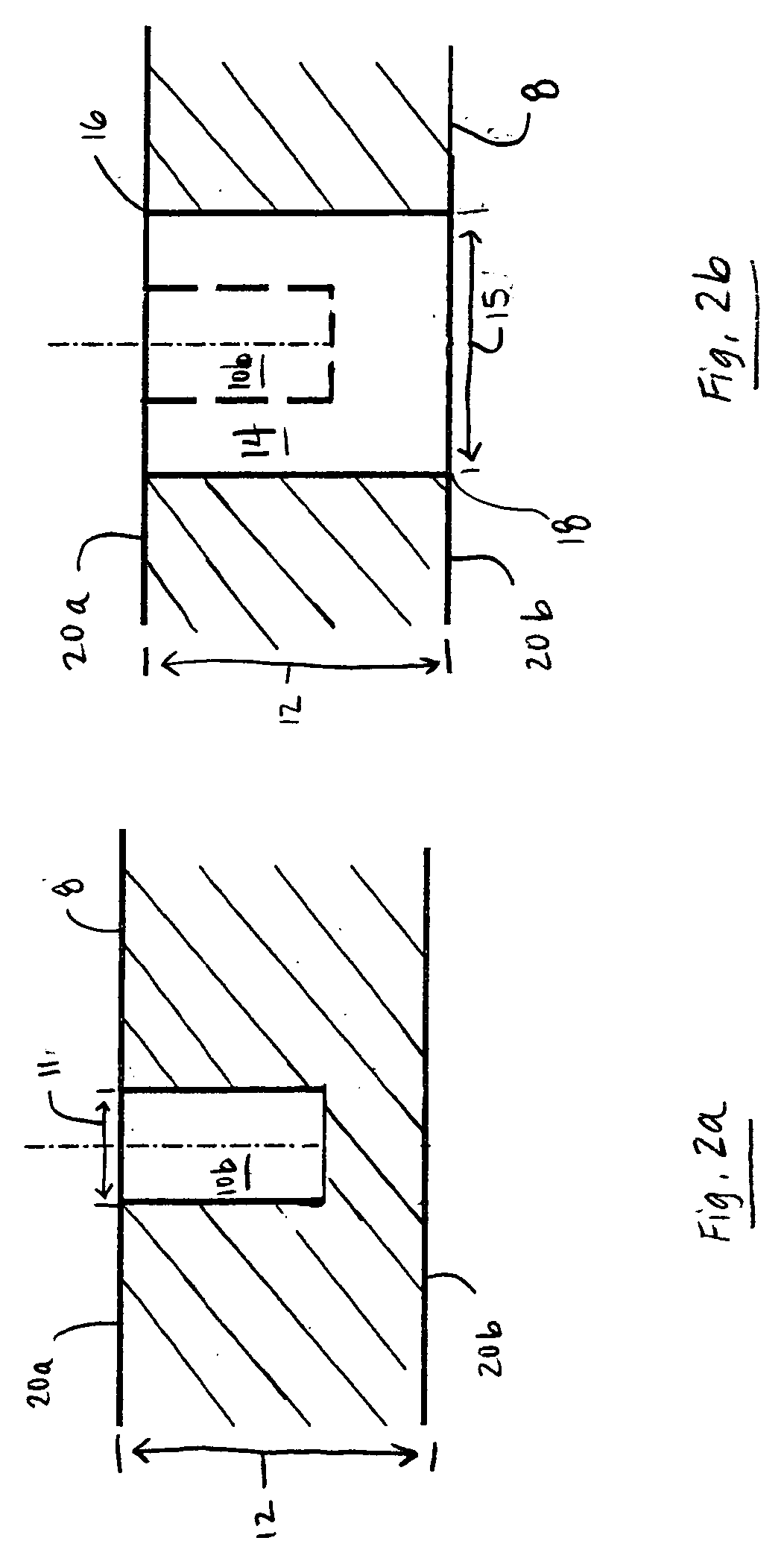
[0022] The present invention is an efficient method of using high-power lasers to effect the controlled removal of target material to form through-holes in a target material. Specifically, the method involves drilling a pilot hole having a diameter that is less than the desired diameter of the through-hole and thereafter drilling the through-hole. With careful selection of the drilling parameters, including the diameter of the pilot hole, pilot hole formation reduces the degree and amount of thermal damage to the heat affected zone surrounding the hole, thereby significantly improving the hole wall surface quality of the drilled through-hole.

[0023] With reference to FIGS. 1a and 1b, in a first preferred embodiment of the present invention, a laser output beam 2 emitted by a high-power laser 4 is directed at a location on a target material 8. For discussion purposes, target material 8 is shown in FIGS. 1a, 1b, 2a, 2b, 3a, and 3b as a homogeneous material, but the invention is also a...


PUM

PropertyMeasurementUnit
diameteraaaaaaaaaa
wavelengthaaaaaaaaaa
vaporization temperaturesaaaaaaaaaa

Abstract

A differential diameter hole drilling method by which through-holes having improved major surface quality are formed in a target material involves drilling a pilot hole having a diameter that is less than the desired diameter of the through-hole and then drilling a through-hole having the desired diameter. The pilot hole forms a channel from which thermal energy produced during laser drilling can diffuse into the environment, thereby reducing the amount of thermal energy diffusing into the surrounding target material matrix and the degree of thermal damage to the heat affected zone of the target material matrix. The pilot hole also forms a channel through which ablated target material may be removed, thereby increasing overall through-hole throughput. Pilot hole formation reduces the thermal energy required to form the remaining portion of the through-hole and thereby results in less thermal damage to the surrounding target material matrix.

Description

TECHNICAL FIELD [0001] The invention relates to laser micromachining and, in particular, to the use of high-power lasers to effect removal of substrate material and thermal energy added during through-hole formation. BACKGROUND OF THE INVENTION [0002] Through-hole drilling is a basic process carried out in the microelectronics manufacturing industry. Exemplary target materials in which through-holes are typically drilled include multi-chip modules (MCMs), ball grid arrays, pin grid arrays, circuit boards, glass cloths (including FR4), hybrid microcircuits, and semiconductor microcircuits. These target materials typically include separate component layers of metal, organic dielectric, and / or reinforcement materials. Through-holes are typically drilled mechanically; however, the growing need for small diameter (e.g., less than 150 microns) through-holes has made mechanical drilling of them impracticable. As the need for small-diameter through-holes increases, there is a consequent inc...

Claims


Application Information

Patent Timeline
Patent Type & Authority Applications(United States)
IPC IPC(8): B23K26/38B23K26/40H01L21/768H01L23/48H05K3/00
CPCB23K26/383B23K26/4045H01L2924/0002H05K2203/1476H05K2203/108B23K26/4075H01L21/76898H01L23/481H01L2924/09701H05K3/0026H05K3/0038H01L2924/00012H01L2924/00B23K26/40B23K26/384B23K2103/36B23K2103/50B23K26/382H01L21/768H01L23/48H05K3/00
Inventor LEI, WEISHENGDAVIGNON, JOHN J.
Owner ELECTRO SCI IND INC
Learn More