

Upper vehicle-body structure of vehicle
a vehicle body and vehicle body technology, applied in the direction of vehicle components, superstructure sub-units, transportation and packaging, etc., can solve problems such as torsional rigidity, and achieve the effect of improving the torsional rigidity of the vehicle body and improving the maneuverability/stability of the vehicl
- Summary
- Abstract
- Description
- Claims
- Application Information
AI Technical Summary
Benefits of technology
Problems solved by technology
Method used
Image

Examples
embodiment 1
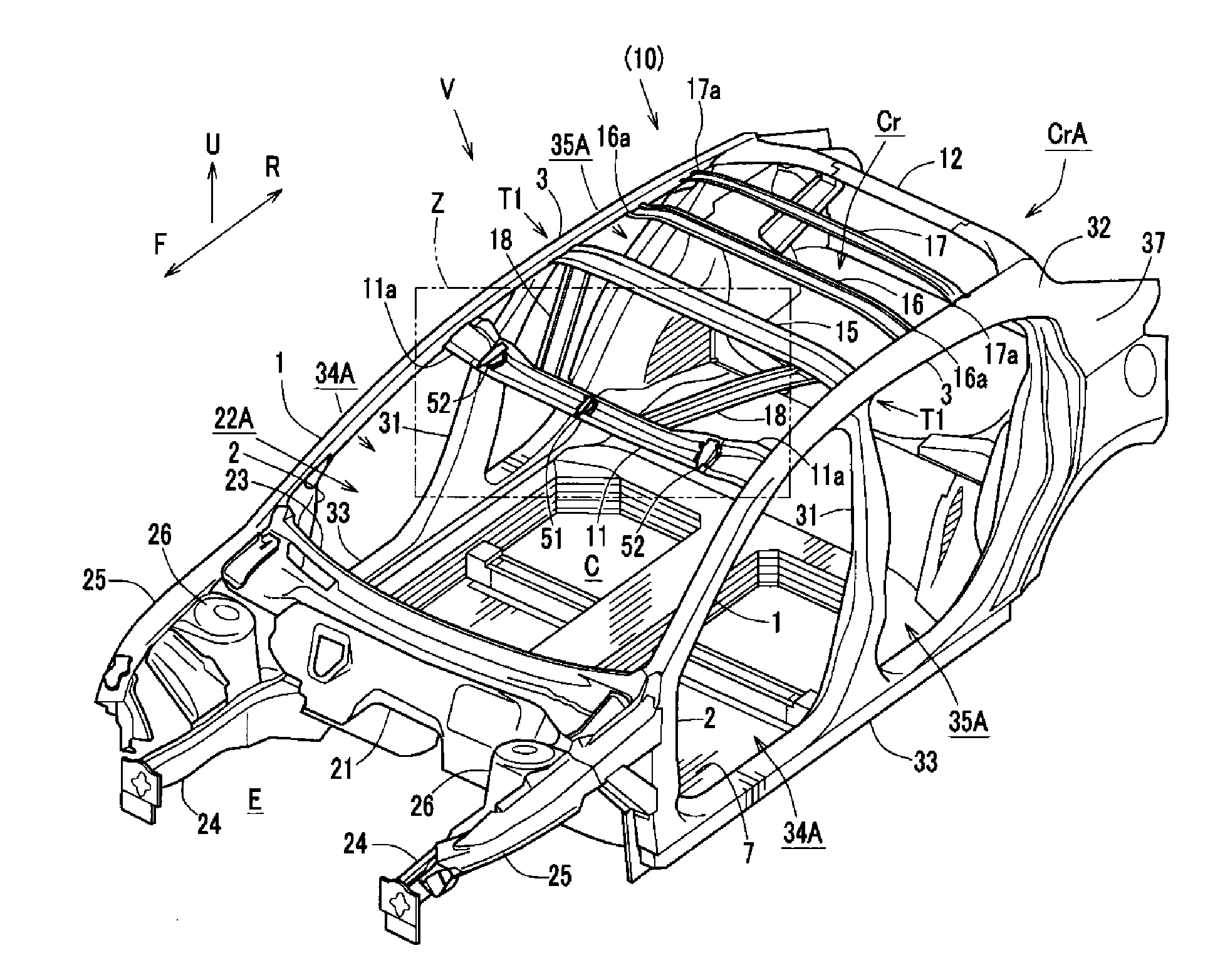
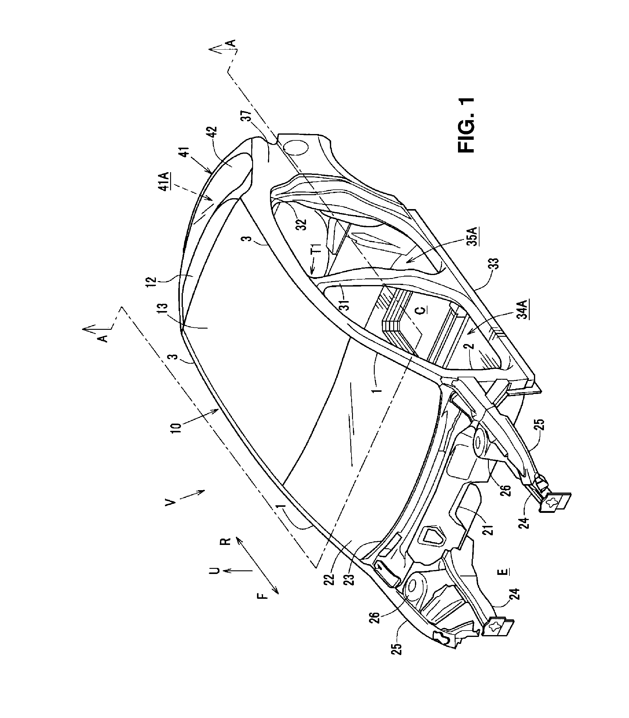
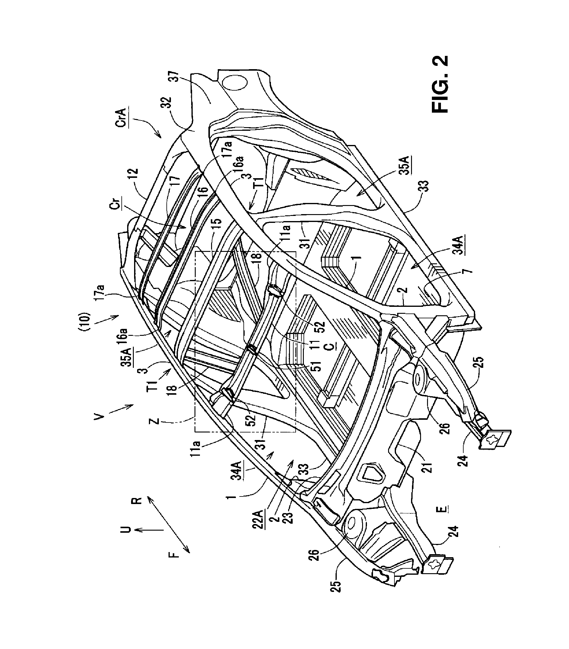
[0031]As shown in FIGS. 1 and 2, a pair of front pillars 1, 1 which extend obliquely upward and rearward from a lower portion of a front side at both sides, in a vehicle width direction, of a vehicle are provided at an upper portion of a vehicle V according to a first embodiment. And, respective lower portions of the front pillars 1, 1 connect to a pair of hinge pillars 2, 2 which extend in a vertical direction.
[0032]The front pillar 1 is a vehicle-body rigidity member having a closed cross section, which is formed by joining a front pillar inner and a front pillar outer, and also the hinge pillar 2 is another vehicle-body rigidity member having a closed cross section, which is formed by joining a hinge pillar inner and a hinge pillar outer.
[0033]As shown in FIGS. 1-3, a pair of right-and-left roof rails 3, 3 (roof side rails) which extend in a vehicle longitudinal direction, respectively, are provided to connect to rear ends of the above-described right-and-left front pillars 1, 1,...
embodiment 2
[0070]A vehicle Va of the second embodiment comprises, as shown in FIG. 8, a pair of right-and-left rear inclination roof reinforcements 61 which are, as shown in FIG. 8, configured such that their rear portions are joined to the rear header 12 and they extend obliquely forward and outward, in place of the rear-side first vehicle-width-direction roof reinforcement 16 and the rear-side second vehicle-width-direction roof reinforcement 17 which the vehicle V of the first embodiment comprises.
[0071]Specifically, the rear inclination roof reinforcements 61 are configured such that their rear portions are joined together to a central portion, in the vehicle width direction, of the rear header 12 via a rear-end flange portion 61ar, and configured in a roughly V shape in the plan view such that the lateral distance thereof becomes larger toward the vehicle front.
[0072]Moreover, as shown in FIG. 8, respective front portions of the rear inclination roof reinforcements 61 are joined to the ro...
embodiment 3
[0077]A vehicle Vb of the third embodiment comprises, as shown in FIG. 9, a front-side cross-shaped roof reinforcement 71 which is configured to extend in the vehicle width direction in a cross shape in the plan view between the pair of right-and-left roof rails 3, 3, in place of the front-side vehicle-width-direction roof reinforcement 15 extending straightly in the vehicle width direction (see FIG. 3) which the vehicle V of the first embodiment comprises.
[0078]The front-side cross-shaped roof reinforcement 71 is configured in the cross shape to have a cross portion which is located at a roughly central position, in the vehicle width direction, of the vehicle body and also at a roughly middle position, in the vehicle longitudinal direction, between the front header 11 and the hinge pillar 2, and to have right-and-left cross portions which are located where this reinforcement 71 crosses a pair of front inclination roof reinforcements 18.
[0079]The front-side cross-shaped roof reinfor...
PUM
 Abstract
Description
Claims
Application Information