Method and device for raising and/or lowering an exhaust gas temperature of a combustion engine having an exhaust gas aftertreatment device arranged in an exhaust line

a technology of exhaust gas aftertreatment and combustion engine, which is applied in the direction of machines/engines, mechanical equipment, electrical control, etc., can solve the problems of ineffective or not very effective exhaust gas catalyst, insufficient conversion rate of reaction, and additional components, so as to achieve the effect of raising and/or lowering and avoiding the disadvantage of conventional systems

Active Publication Date: 2016-08-18
MAN TRUCK & BUS AG
View PDF1 Cites 9 Cited by
  • Summary
  • Abstract
  • Description
  • Claims
  • Application Information

AI Technical Summary

Benefits of technology

[0009]It is thus an object of the present invention to provide an improved method and an improved device for raising and / or lowering an exhaust gas temperature of a combustion engine having an exhaust gas aftertreatment device arranged in an exhaust line, by which disadvantages of conventional systems can be avoided.

Problems solved by technology

Below this light off temperature, the exhaust gas catalyst is ineffective or not very effective, and the reaction takes place only at insufficiently low conversion rates.
The disadvantage with the abovementioned approaches is that additional components, e.g., a burner system, an engine braking flap, etc., have to be provided and disadvantages in terms of efficiency have to be accepted.
The disadvantage of this technique is that an additional introduction device is necessary.
This system is of complex construction and requires a large number of specially manufactured components.
Moreover, effective control is only possible in relation to the raising of the exhaust gas temperature.

Method used


Image

  • Method and device for raising and/or lowering an exhaust gas temperature of a combustion engine having an exhaust gas aftertreatment device arranged in an exhaust line
  • Method and device for raising and/or lowering an exhaust gas temperature of a combustion engine having an exhaust gas aftertreatment device arranged in an exhaust line
  • Method and device for raising and/or lowering an exhaust gas temperature of a combustion engine having an exhaust gas aftertreatment device arranged in an exhaust line

Examples


Embodiment Construction

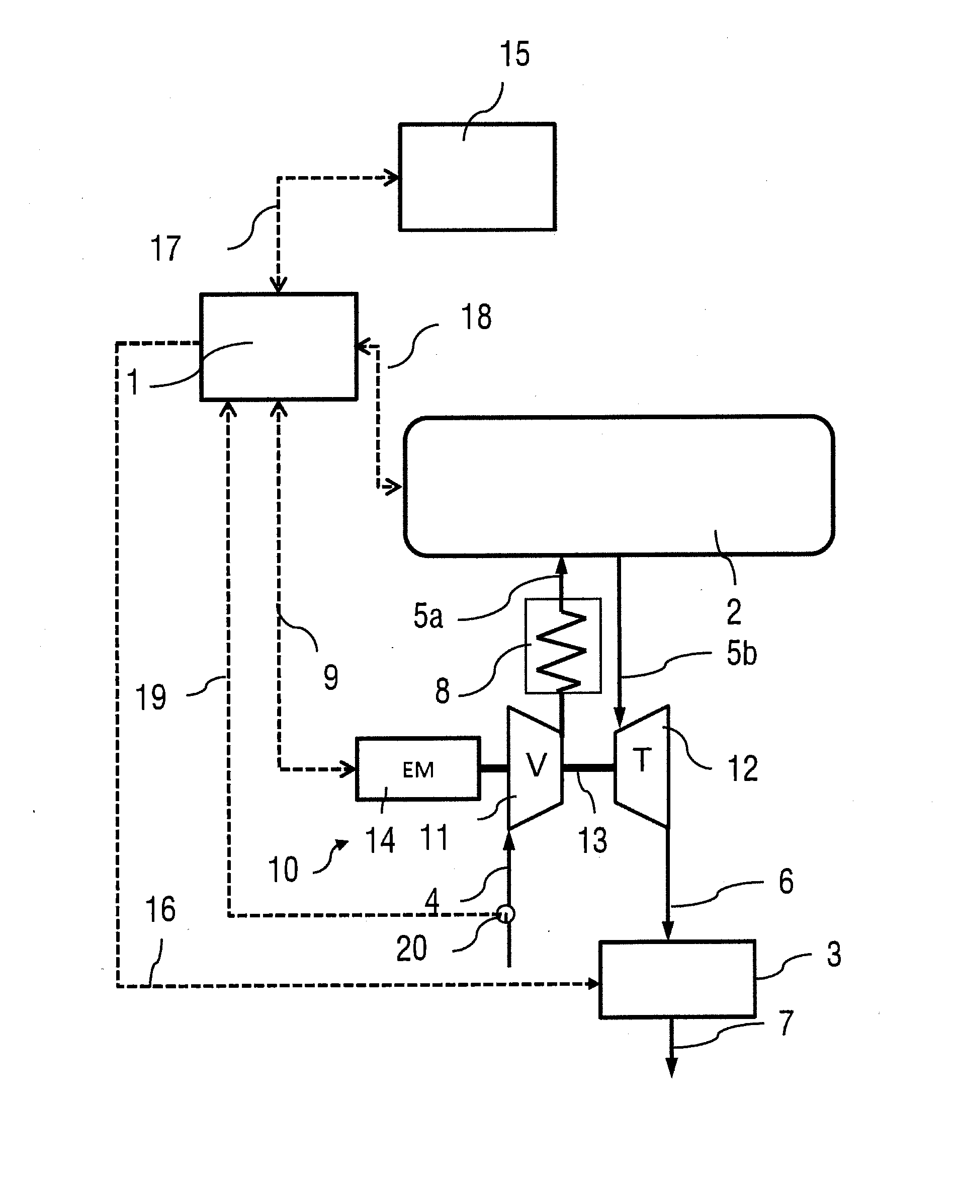
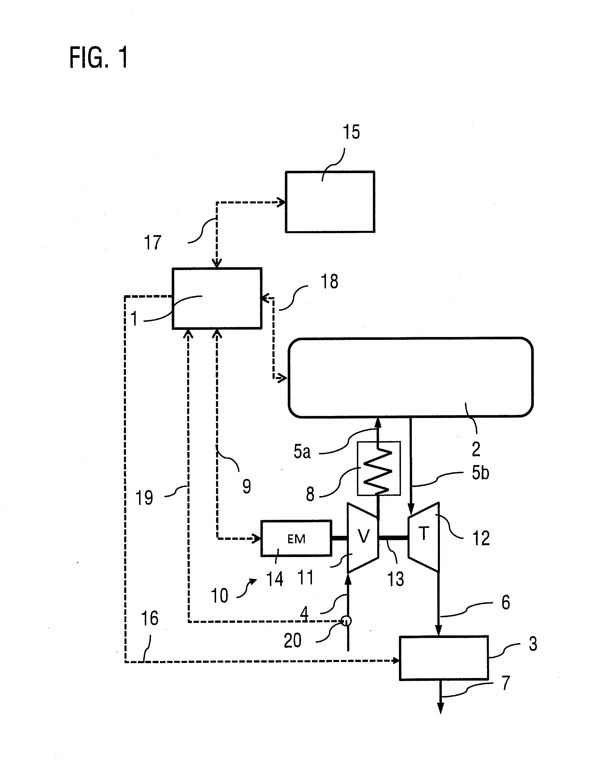
[0033]FIG. 1 schematically shows a pressure-charged combustion engine 2 of a commercial vehicle, typically a diesel engine, and an electrified exhaust turbocharger 10 associated therewith, also referred to below as ETC, in the form of a highly schematized block diagram. The ETC 10 comprises a turbine 12, which is driven by the exhaust gas from the combustion engine 2, which is fed to the turbine 12 via the exhaust line 5b. After this, the exhaust gas mixture flows via the turbine outlet through an exhaust line 6, in which an exhaust gas aftertreatment device 3 known per se, e.g., in the form of an exhaust catalyst, is arranged. After passing through the exhaust gas aftertreatment device 3, the exhaust gas flows via another exhaust line 7 to the exhaust.

[0034]The turbine 12 is connected to a compressor 11 by a shaft 13. Fresh air is fed to the compressor 11 via the compressor inlet line 4. The compressor 11 compresses the charge air to be fed to the combustion engine 2 and thus boost...


PUM


Abstract

A method and a control device for raising and/or lowering an exhaust gas temperature of a combustion engine having an exhaust gas aftertreatment device arranged in an exhaust line sets the exhaust gas temperature for the exhaust gas aftertreatment using an electric-motor mode and/or a generator mode of an electrified exhaust turbocharger.

Description

BACKGROUND OF THE INVENTION[0001]1. Field of the Invention[0002]The invention relates to a method for raising and / or lowering an exhaust gas temperature of a combustion engine having an exhaust gas aftertreatment device arranged in an exhaust line. The invention furthermore relates to a control device for raising and / or lowering an exhaust gas temperature of a combustion engine having an exhaust gas aftertreatment device arranged in an exhaust line.[0003]2. Related Art[0004]The fact that pollutant emissions from a combustion engine can be reduced in an effective manner by catalytic aftertreatment of the exhaust gas with the aid of an exhaust gas aftertreatment system, e.g., one having an exhaust gas catalyst, is known from practical experience. However, it is an important precondition for this that the catalyst has reached its light off temperature. Below this light off temperature, the exhaust gas catalyst is ineffective or not very effective, and the reaction takes place only at i...

Claims


Application Information

Patent Timeline
Patent Type & Authority Applications(United States)
IPC IPC(8): F02D41/02F02D41/00F01N3/20
CPCF02D2041/0265F02D41/024F02B39/10F01N3/0235F02D41/0245F02D41/0007F01N2240/14F01N2240/36F01N3/2046F01N3/025F01N13/08F01N3/02F01N2430/08Y02A50/20Y02T10/12
Inventor PAPPENHEIMER, ANDREASSOMMERMANN, ANDREAS
Owner MAN TRUCK & BUS AG
Why Eureka
Try Eureka