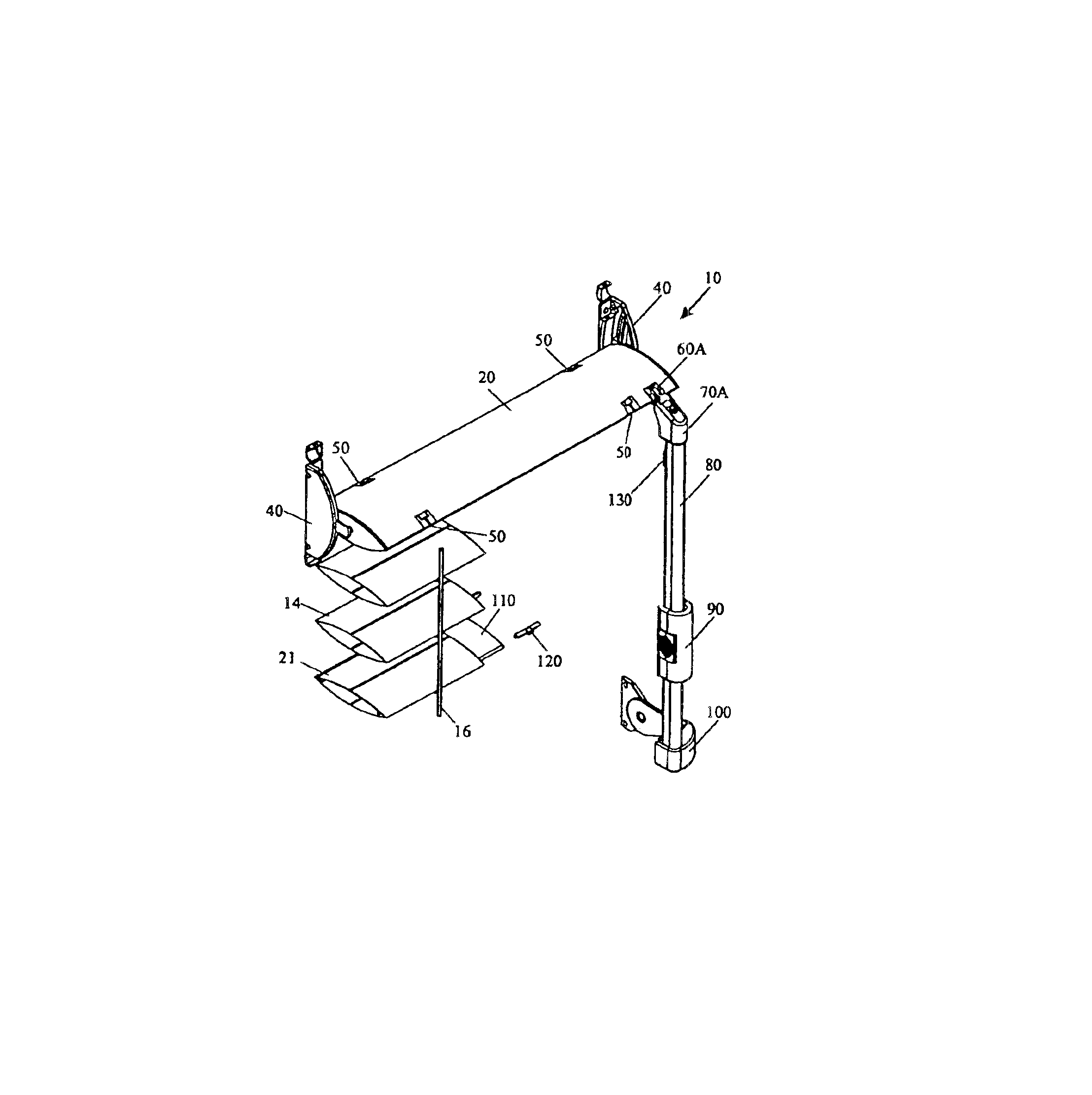
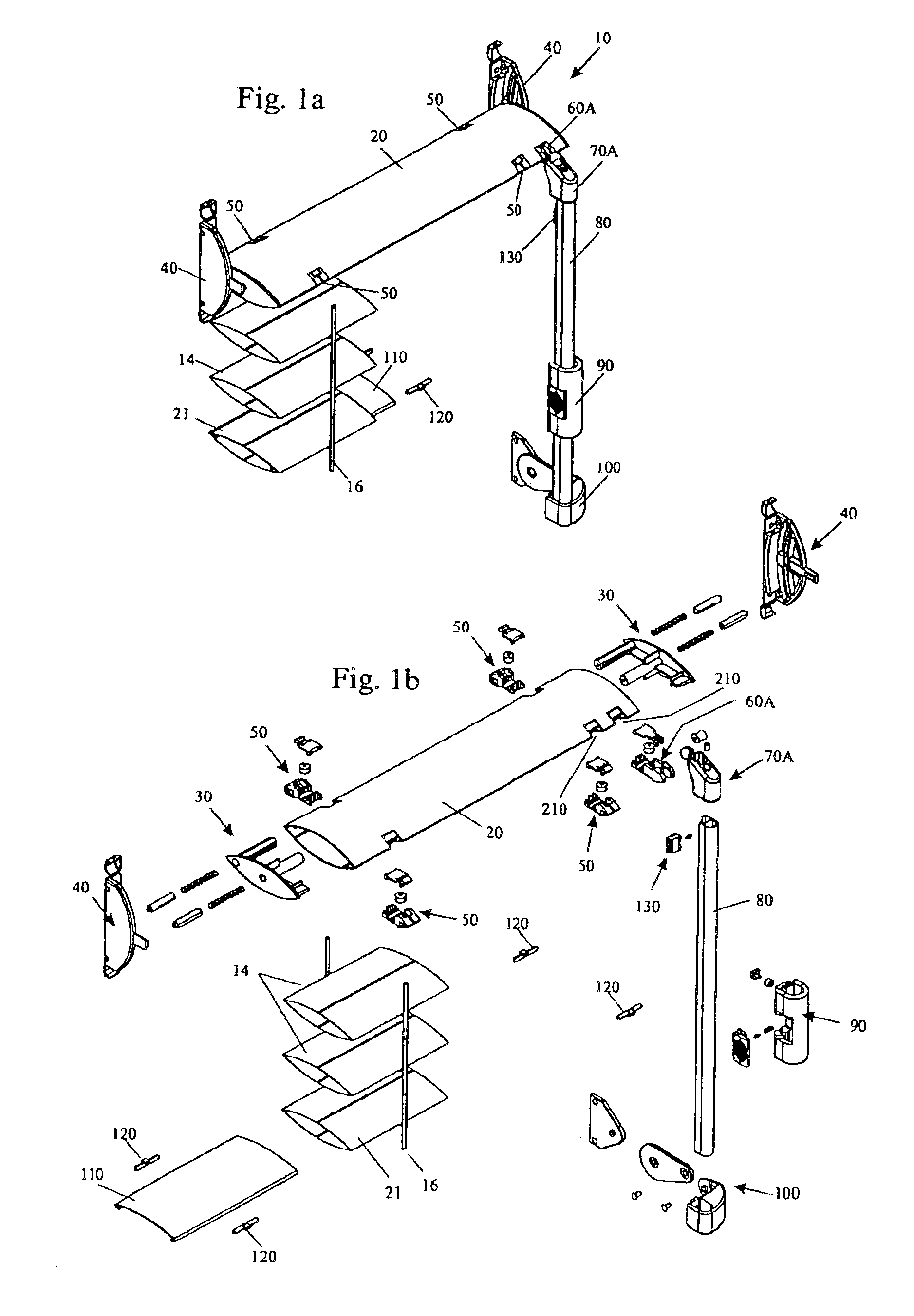
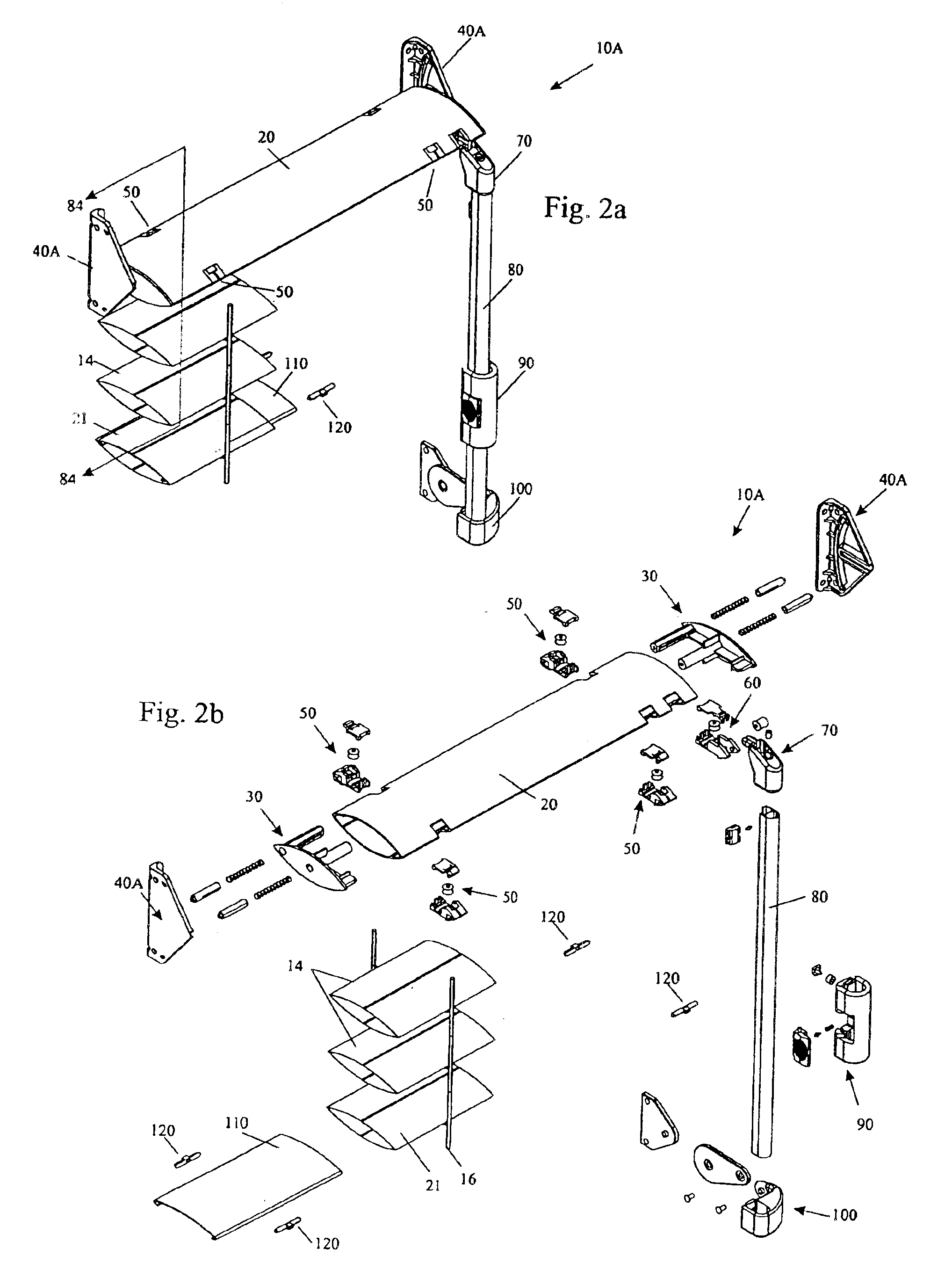
Shutter-like covering and hardware for architectural opening
a technology for shutters and openings, applied in the field of shutters for architectural openings, can solve the problems of not hiding the mechanism used to raise, lower, open and close blinds, and the effort required to raise the stack is too large to be comfortable and convenient for users, and the louver cannot be raised or lowered
- Summary
- Abstract
- Description
- Claims
- Application Information
AI Technical Summary
Benefits of technology
Problems solved by technology
Method used
Image
Examples
second embodiment
[0322]FIGS. 42 through 44 show the adjustable bottom end cap 150A. As may be seen in FIG. 42D, the shape of the bottom end cap 150A is similar to the shape of the bottom end cap 150 of FIG. 40B, the main difference being that there is an upwardly-projecting post 1514A within the cavity 1502A instead of the serrations 1506 of the previous embodiment. The post 1514A has a wing-nut shaped hole 1516A toward the free end of the post 1514A. The wing-nut shaped hole 1516A is a vertical slot, with an enlarged central portion. A lever 1518A (See FIG. 42E) is used to lock the end cap 150A to the tilt bar 80 at various heights. The lever 1518A has an arm 1520A with a first end 1522A and a second end 1524A. The first end 1522A has a flat head 1526A, while near the second end 1524A there is a stub shaft 1528A, with an enlarged nub 1530A extending to one side and a rectangular block 1532A extending from the opposite side. The nub 1530A on the stub shaft 1528A is snapped through the enlarged centr...
first embodiment
[0362]Referring to FIGS. 86B and 87B, simply raising the grip housing 1902 also raises the cover housing 1904 (since they are interconnected via the slotted ridges 1966 and the slotted crevice 1962) so that the tab 1954 of the lower bracket 1950 is also raised until it impacts against the bottom surface 1938 of the pivoting lock arm 1912, thus unlocking the hand control 190 and allowing the hand control 190 to be raised by the lower leg 1952 of the “L”-shaped bracket 1950, as shown in FIG. 87B. By the same token (See FIG. 88B), simply lowering the grip housing 1902 also lowers the cover housing 1904, so that the upper bracket 1946 pushes down onto the pulley housing 1906, canceling out the upward force of the lift cord 12 that is wrapped around the pulley 1910. Once the upward force of the lift cord is overcome by the downward force of the person pulling down the hand control, the pivoting lock arm 1912 releases its grip on the tilt bar 80, and downward motion of the hand control 19...
fifth embodiment
[0377]FIGS. 72A, 72B, 73A, and 73B depict a pivot bracket 100D, which may be used instead of any of the previously described pivot brackets 100, 100A, 100B, 100C. Once again, the bottom attachment 1002D, and the connecting arm 1004D are present and readily recognizable, while the frame attachment may be from any one of the previously described mounting brackets, such as the mounting bracket 40B shown in FIG. 72A. Thus, the connecting arm 1004D very closely resembles part of the air foil shaped end cap 30A (See FIGS. 20A and 73A) which was designed to mount to mounting bracket 40B. The advantage of this pivot bracket 100D is that, without actually being directly connected to the bottom louver 21, the connecting arm 1004D looks like an end cap for the bottom rail 21 and mimics the motion of the bottom rail 21 even as the bottom rail 21 tilts closed and traverses toward the wall or tilts open and traverses away from the wall.
[0378]FIGS. 73C and 73D depict a sixth embodiment of a pivot ...
PUM
 Abstract
Description
Claims
Application Information
 - R&D
- Intellectual Property
- Life Sciences
- Materials
- Tech Scout
- Unparalleled Data Quality
- Higher Quality Content
- 60% Fewer Hallucinations
Browse by: Latest US Patents, China's latest patents, Technical Efficacy Thesaurus, Application Domain, Technology Topic, Popular Technical Reports.
© 2025 PatSnap. All rights reserved.Legal|Privacy policy|Modern Slavery Act Transparency Statement|Sitemap|About US| Contact US: help@patsnap.com


