Portable studio hoist

a hoist and studio technology, applied in the field of portable hoists, can solve the problem that standard hoists cannot be added to building steel

Inactive Publication Date: 2007-07-17
MEDTRONIC INC +1
View PDF18 Cites 25 Cited by
  • Summary
  • Abstract
  • Description
  • Claims
  • Application Information

AI Technical Summary

Benefits of technology

[0006]The invention is generally directed to a portable studio hoist, which includes a mechanism for removably connecting the portable studio hoist to the pipe grid structure used in television and theatrical studios and performance venues, which allows studio lighting fixtures to be raised and lowered from the grid to different operating positions and the floor safely and without the need for dedicated wiring or structural modifications to the theater and studio to support the hoist.
[0008]Accordingly, it is an object of the invention to provide an improved portable hoist to improve access to lighting fixtures and efficiency of broadcast studios by allowing studio lighting fixtures to be raised and lowered from the pipe grid without having to bring in special power or structural elements to the pipe grid.
[0009]It is another object of the invention is to provide an improved portable hoist for use in theater and studio applications utilizing a single-phase 120 VAC current which may be removably secured to the pipe grid wherever it is needed without the need for special tools or additional installation hardware.
[0011]Still another object of the invention is to provide an improved portable hoist in which the shaft may be replaced by the end user without affecting the operation of the hoist.
[0012]Yet still a further object of the invention is to provide an improved portable hoist which may be connected either parallel to the standard pipes of the pipe grid or at an angle to the pipe grid so as to provide enhanced flexibility of positioning of the portable hoist.

Problems solved by technology

Generally, standard hoists can only be added to the building steel or with the addition of structural steel because the pipe grid does not have sufficient weight bearing capacity to support the weight of these hoists, and lifted weight, which generally run about 750 or more pounds.

Method used


Image

  • Portable studio hoist
  • Portable studio hoist
  • Portable studio hoist

Examples


Embodiment Construction

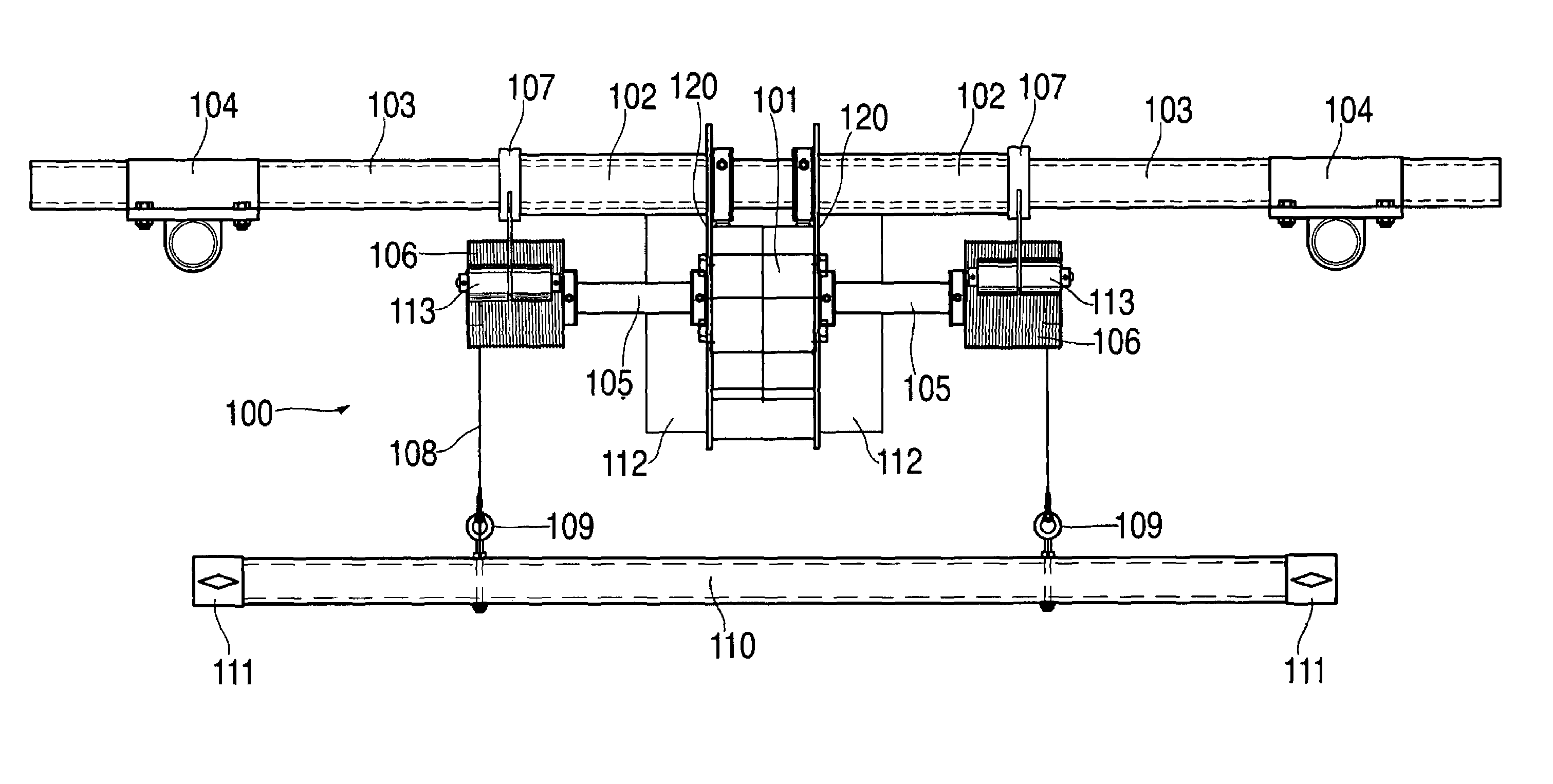
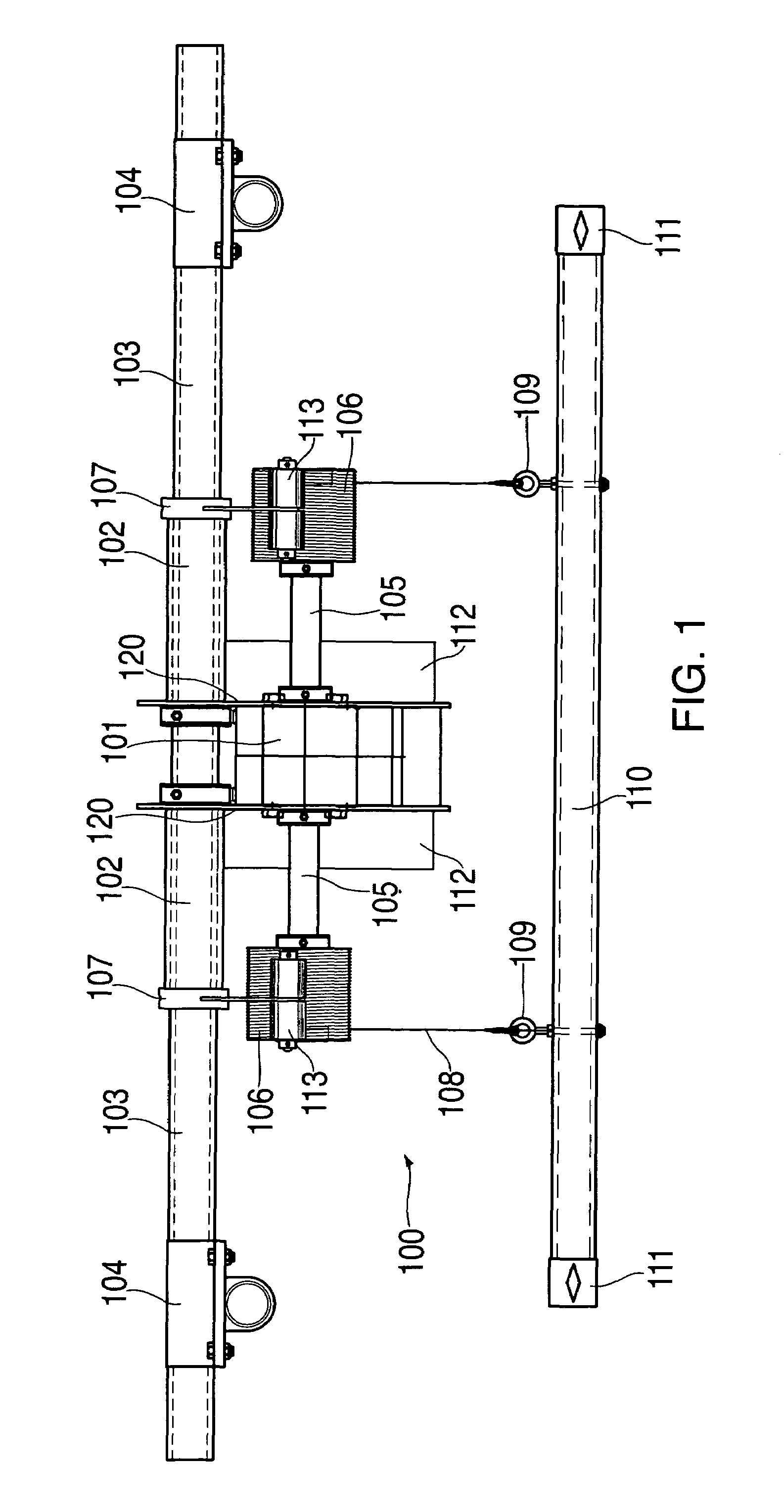
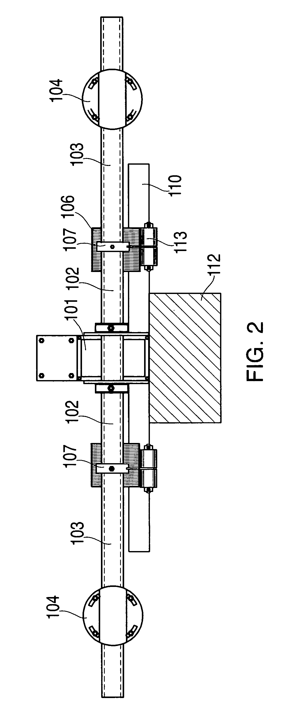
[0027]The portable hoist was developed to address the need for a safe, low cost and portable hoist to improve access to lighting fixtures and efficiency of broadcast studios. While existing hoists in theater and studio applications are intended for permanent installation and typically must be installed as part of the building construction project, the portable studio hoist constructed in accordance with a preferred embodiment of the invention is easily movable and portable in existing studios.

[0028]In a preferred embodiment the portable studio hoist weights only about 90 pounds and can be moved by two stage hands anywhere on the pipe grid found in most U.S. television studios and many theatrical and other studio installations. The compactness, light weight and connection details are specifically designed for attachment to a standard 1½ inch schedule 40 pipe grid. The portable studio hoist can also be attached to other installations, other than a pipe grid with suitable connectors. T...


PUM


Abstract

A portable studio hoist which can be positioned and secured in a studio pipe grid or other structural setting without the need for hard wired power supplies or fixed attachments. The portable studio hoist is designed to operate on standard single phase 120 volt power and includes a motor mounted to a support bar with a dual cable system for supporting, raising and lowering a batten to which the load is secured. The portable studio hoist allows for easy movement as needed within a studio environment and attachment where needed with provisions for variably orientated attachment relative to the pipe grid. A series of portable studio hoists can be secured around the studio and then controlled remotely from a single location by way of the use of control hubs, to which a series of portable studio hoists are connected, and a selector control station connected to each control hub with a pendant to operate the hoists.

Description

[0001]This application claims the priority of provisional application Ser. No. 60 / 559,208 filed in the United States Patent and Trademark Office on Apr. 2, 2004.BACKGROUND OF THE INVENTION[0002]The invention is generally directed to a portable studio hoist for use in raising and lowering lighting and other items from the pipe grids used in television studios, which are generally suspended from the building structure. The portable studio hoist is utilized to move studio lighting fixtures, which are affixed to the pipe grid vertically between the floor and the pipe grid. It may also be used to move lighting fixtures and other loads in other settings secured to appropriate fixed structural locations[0003]Generally, existing hoists in theater and studio applications are intended for permanent installation, and typically, because of their size, weight and power requirements, must be installed as part of the building construction project. The hoists are affixed to the building's structura...

Claims


Application Information

Patent Timeline
Patent Type & Authority Patents(United States)
IPC IPC(8): B66D1/26A63J1/02A63J5/00B66C13/56B66D1/00F21S8/00F21V9/00F21V21/38
CPCA63J1/028B66C13/56B66D1/00F21V21/38F21W2131/406
Inventor POOK, BARBARA S.DIEMONT, ANTHONY J.OHL, THEODORE G.
Owner MEDTRONIC INC
Why Eureka
Try Eureka