Concealed net throwing device

a technology of a net and a shield, which is applied in the direction of compressed gas guns, white arms/cold weapons, weapons, etc., can solve the problems of not being concealed and compromising the desired function of snarling the robber

Inactive Publication Date: 2016-08-18
TSENG JUI FU
View PDF8 Cites 25 Cited by
  • Summary
  • Abstract
  • Description
  • Claims
  • Application Information

AI Technical Summary

Problems solved by technology

The drawback of the prior art is that it is not concealed.
As a result, the desired function of snarling the robber is compromised.

Method used


Image

  • Concealed net throwing device
  • Concealed net throwing device
  • Concealed net throwing device

Examples


Embodiment Construction

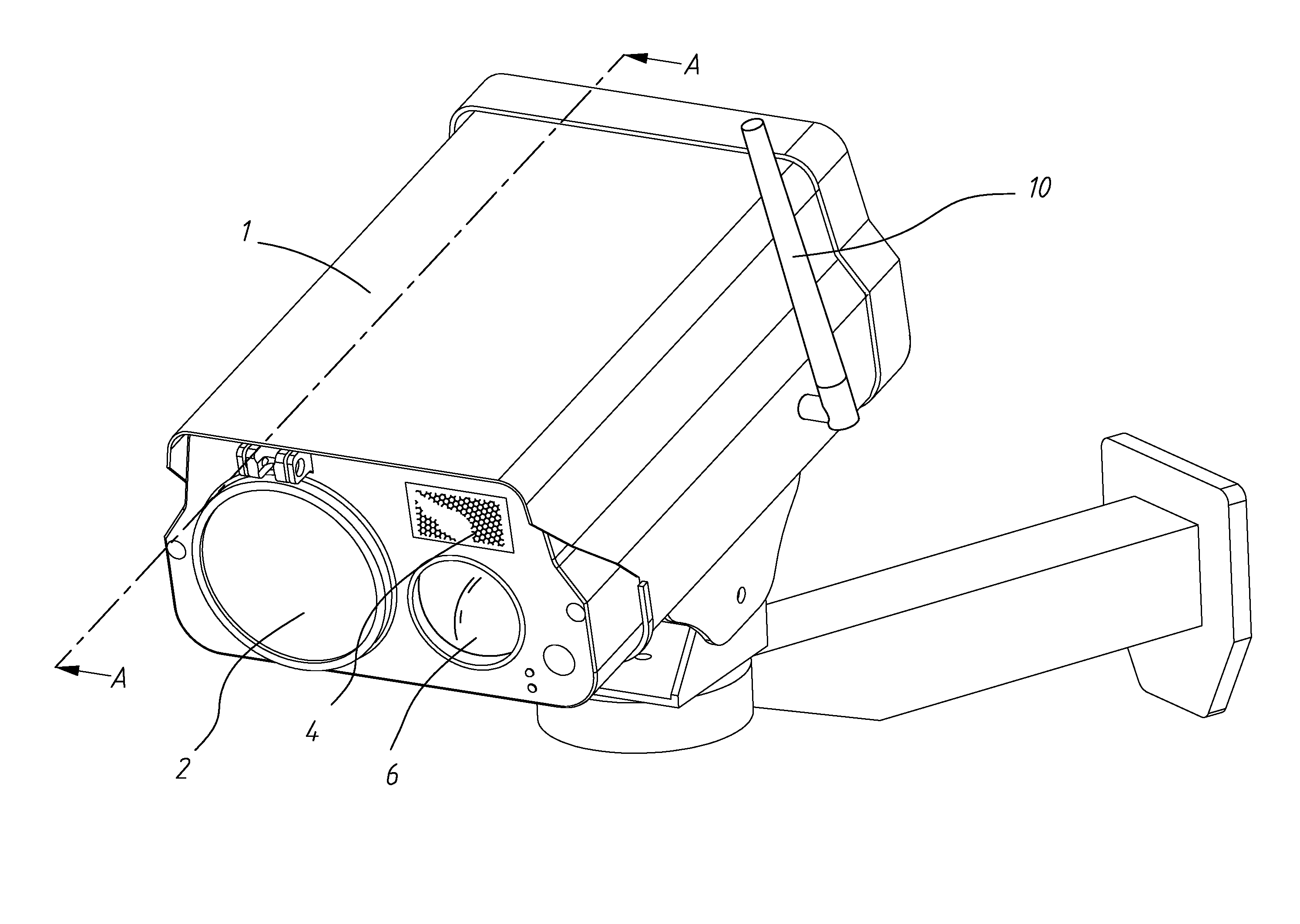
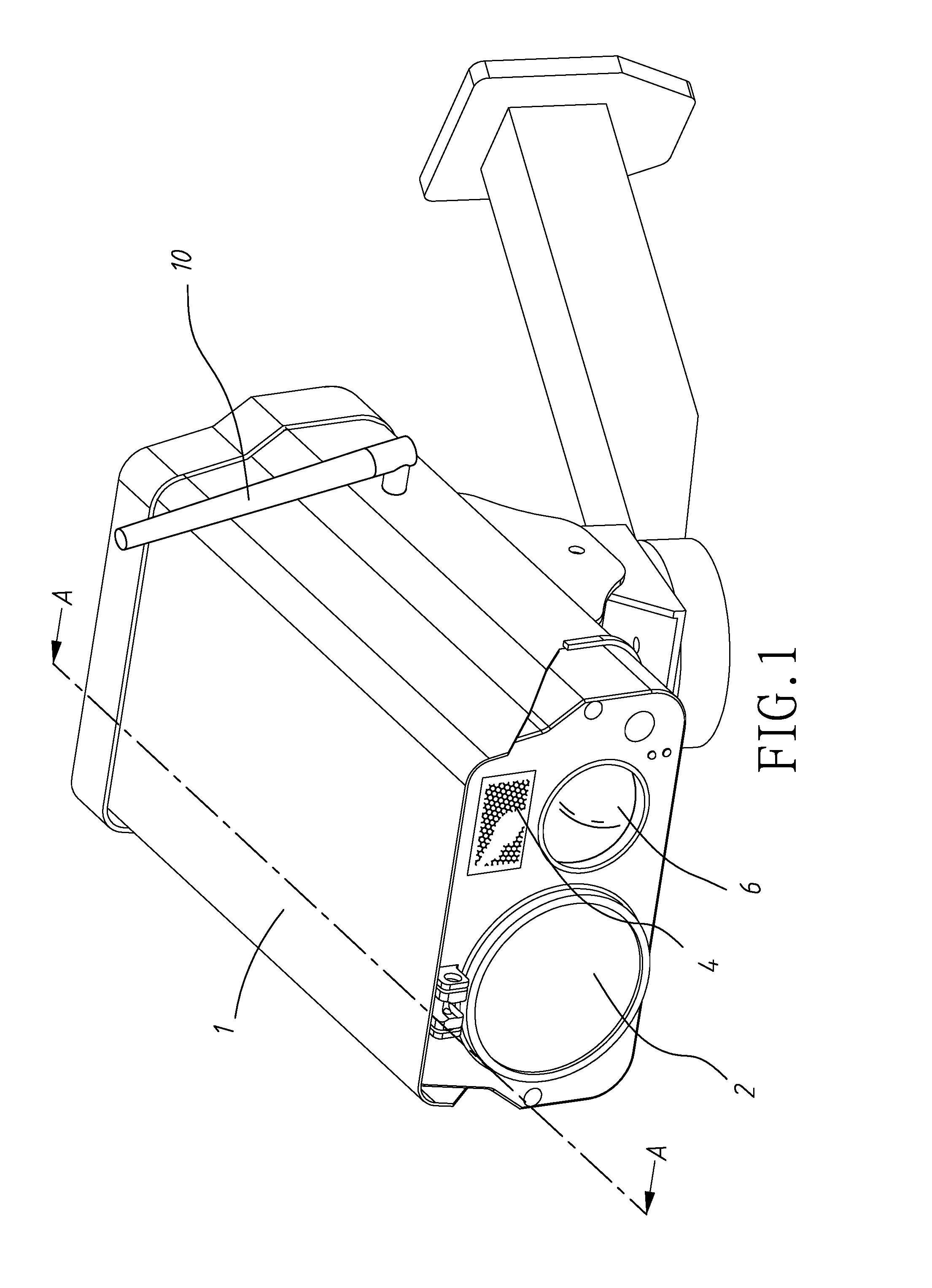
[0018]Referring to FIGS. 1 to 8, a net throwing device in accordance with a first preferred embodiment of the invention is shown as a wall mounted, swiveled one and disguised as a security camera. The net throwing device comprises the following components as discussed in detail below.

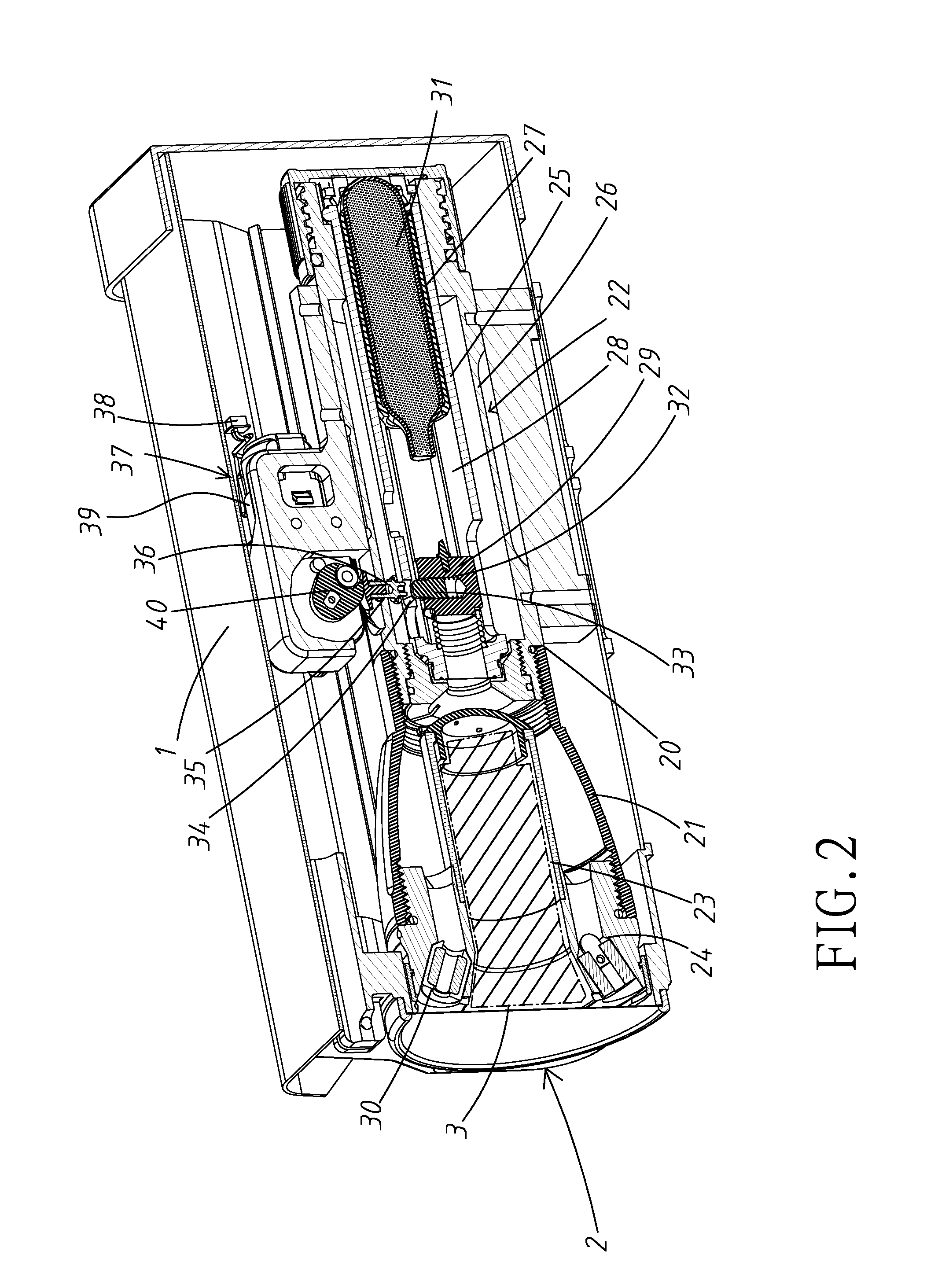
[0019]A casing 1 comprises a launching mechanism 2 including a barrel member 20 having a front section 21 and a rear section 22 threadedly secured to the front section 21. A chamber 23 is provided in the front section 21 for receipt of a net 3. A plurality of inclined tubes 24 are formed around the mouth of the front section 21. A plurality of weights 30 are disposed in the tubes 24 respectively. The weight 30 is connected to the net 3 by a plurality of threads at the edge of the net 3. The rear section 22 is formed as an outer tube 26 with an inner tube 25 disposed therein. A rear cap 27 is threadedly secured to a rear end of the outer tube 26. An air canister 31 is fastened in the inner tube 25 and ha...


PUM


Abstract

A net throwing device is disguised as a security camera and includes a casing including a front chamber, inclined tubes around the front chamber, a rear inner tube having an aperture member, and a rear outer tube having an aperture element; an air canister fastened in the inner tube; a spring biased piercing member slidably disposed between the front chamber and the air canister; a spring biased lock pin in the piercing member and having an end disposed in the aperture member to lock the piercing member in a locked position; a spring biased rod member through the aperture element; a cam member engaging the rod member; an external antenna; a receiver; a processor electrically connected to the receiver; an electric motor electrically connected to the processor; and a net received in the front chamber and including edge weights in the tubes respectively.

Description

BACKGROUND OF THE INVENTION[0001]1. Field of the Invention[0002]The invention relates to restraint devices and more particularly to a net throwing device disguised as a security camera.[0003]2. Description of Related Art[0004]US Publication No. 201 5 / 01 681 07 to Tseng discloses a net throwing device for use in combination with a compressed air powered launching device, comprising a pod comprising an axial space, tubes around the axial space, and a slot formed on an edge; a net in the axial space; weights each in one of the tubes; and a casing comprising a forward oriented projection on an edge of a front end, the forward oriented projection being fitted in the slot to secure the casing and the pod together, and a protrusion adjacent to the forward oriented projection; wherein at least one of the tubes is inclined with respect to an axis of the axial space, and at least one of the tubes is parallel to the axis of the axial space; and wherein the casing communicates with the axial sp...

Claims


Application Information

Patent Timeline
Patent Type & Authority Applications(United States)
IPC IPC(8): F41H13/00F41B11/80
CPCF41B11/80F41H13/0006F41C9/02
Inventor TSENG, JUI-FU
Owner TSENG JUI FU
Why Eureka
Try Eureka