Coin depositing and dispensing machine

a coin depositing and coin dispenser technology, applied in coin dispensers, coin counters, instruments, etc., can solve the problems of limited installation space of coin depositing and dispensing machines, large machine body size apparatus errors, so as to reduce the size of the machine body in the depth direction, reduce the coin storing capacity, and simple structure

Active Publication Date: 2016-08-18
GLORY KOGYO KK
View PDF4 Cites 2 Cited by
  • Summary
  • Abstract
  • Description
  • Claims
  • Application Information

AI Technical Summary

Benefits of technology

[0012]The present invention has been made in view of the above circumferences. The object of the present invention is to provide a coin depositing and dispensing machine in which a plurality of storing and feeding units are vertically arranged on plural levels, and the respective storing and feeding units are arranged such that a transport direction in which a coin is transported by a deposited-coin transport unit and a feeding direction in which a coin is fed out from each storing and feeding unit are substantially perpendicular to each other, whereby a size of a machine body in a depth direction can be reduced, without decrease in coin storing capacities of the respective storing and feeding units.
[0013]Another object of the present invention is to provide a coin feeding apparatus in which a rotating disk is provided with a coin elimination unit so that two or more coins are prevented from being simultaneously fed out by a guide member to an outside of the rotating disk, and a coin depositing and dispensing machine including the coin feeding apparatus.
[0014]Yet another object of the present invention is to provide a money handling apparatus in which installation of a collection box can be omitted, the money handling apparatus being capable of suitably performing a collection operation for collecting collection money other than overflow money, by selectively performing any one of a first mode in which collection money is sent from a transport unit to an overflow unit and a second mode in which collection money is sent from the transport unit to a money dispensing opening.
[0015]Still another object of the present invention is to provide a coin feeding apparatus, a coin depositing and dispensing machine and a coin feeding method which are capable of preventing an excessive coin from being fed to an outside from the coin feeding apparatus by a simple structure without providing any additional member such as a delivery disk, in which, when coins of the preset number have been fed to an outside through a coin outlet, a rotating disk is stopped at a position where a projecting member disposed on the rotating disk blocks the coin outlet, whereby a coin in excess of the preset number can be reliably prevented from being fed out to the outside from the coin outlet.

Problems solved by technology

In the conventional coin depositing and dispensing machines disclosed in Patent Document 1, Patent Document 2 and so on, since the plurality of storing and feeding units are arranged along the coin transport path extending in the depth direction of the machine body, the following problems occurs.
Namely, the size of the machine body in the depth direction is large, whereby an installation space of the coin depositing and dispensing machine is limited.
In this case, when the two or more coins having been caught by the one projecting member are simultaneously fed out by the guide member to the outside of the rotating disk, a problem such as jam might occur in a coin transporting mechanism provided on a downstream side of the coin feeding apparatus, resulting in apparatus error.
In addition, when the two or more coins are simultaneously fed out to the outside of the rotating disk, a count sensor disposed on an outlet of the coin feeding apparatus may possibly count the number of coins as one, which leads excessive feeding and miscount.
In addition, in the conventional coin depositing and dispensing machine disclosed in Patent Document 4, since the three storing means, i.e., the coin storing and feeding unit, the collection box and the overflow box should be provided, there are problems in that the structure inside the machine body is complicated as well as an outer shape of the coin depositing and dispensing machine is large.
Thus, even when the operation for replenishing the coin storing and feeding unit with the coins in the overflow box is performed plural times, the collection coin remains forever in the overflow box, whereby the collection coin cannot be suitably collected.
In addition, in the conventional coin feeding apparatus disclosed in Patent Document 3, since the delivery disk should be provided above the rotating disk, an installation space of the delivery disk is needed, which increases an installation space of the apparatus as a whole.
Moreover, the installation of the delivery disk increases cost.

Method used


Image

  • Coin depositing and dispensing machine
  • Coin depositing and dispensing machine
  • Coin depositing and dispensing machine

Examples


first embodiment

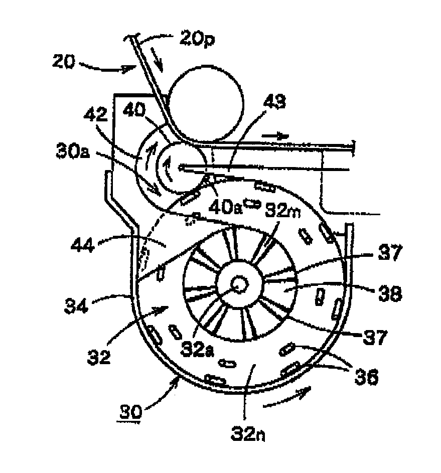
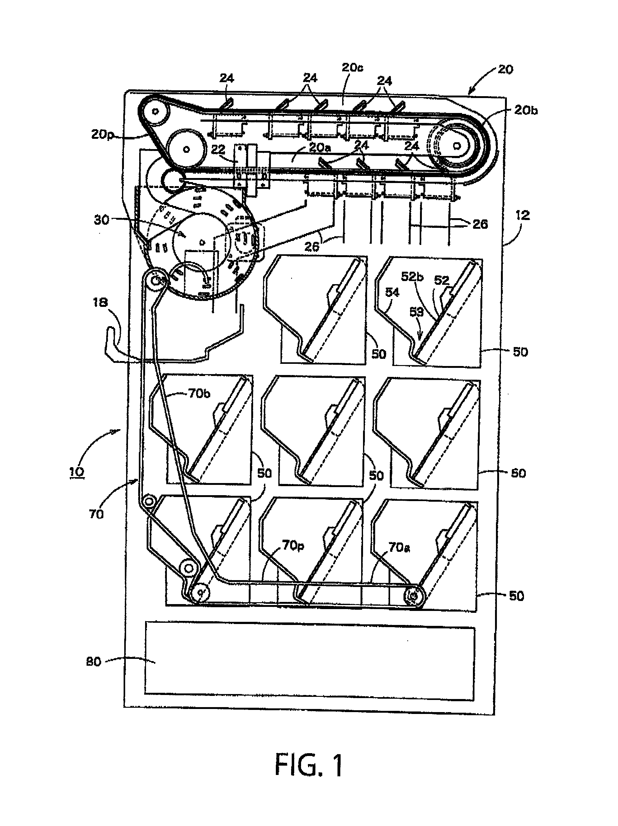
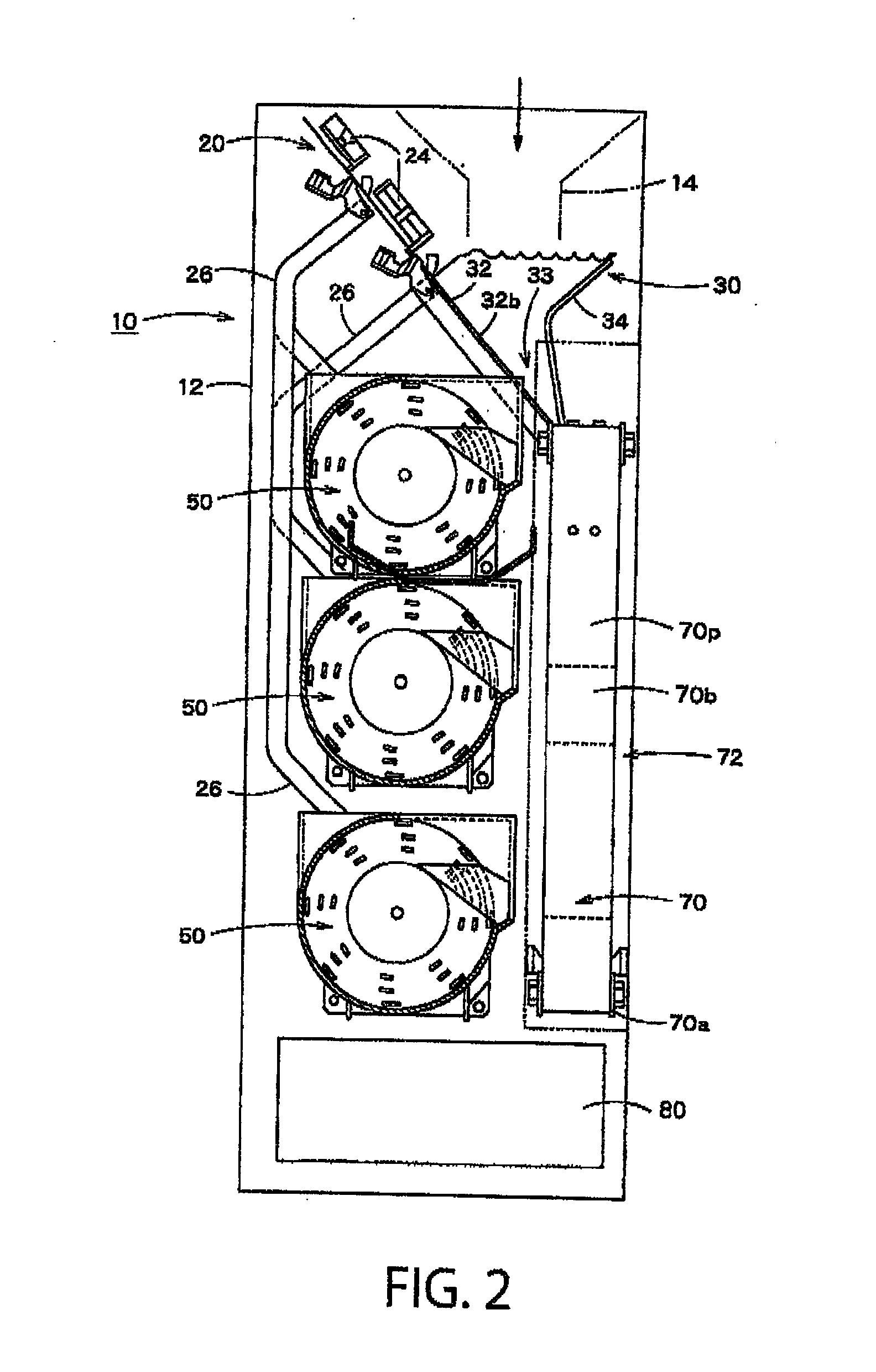
[0141]A first embodiment of the present invention will be described herebelow with reference to the drawings. FIGS. 1 to 8 show a coin depositing and dispensing machine in the first embodiment. FIG. 1 is a side view schematically showing an inside structure of the coin depositing and dispensing machine in the first embodiment, and FIG. 2 is a front view of the coin depositing and dispensing machine shown in FIG. 1. FIGS. 3 and 4(A) and 4(B) are structural views showing a structure of a pooling and feeding apparatus in the coin depositing and dispensing machine shown in FIG. 1 and so on. FIGS. 5(A) and 5(B) are_sectional views showing a structure of a sorting unit in the coin depositing and dispensing machine shown in FIG. 1 and so on. FIGS. 6 to 8 are structural views showing a structure of a storing and feeding apparatus of the coin depositing and dispensing machine shown in FIG. 1 and so on.

[0142]As shown in FIGS. 1 and 2, a coin depositing and dispensing machine 10 includes: a ho...

second embodiment

[0210]Herebelow, a second embodiment of the present invention will be described with reference to the drawings. FIGS. 11 to 14 are views showing a coin depositing and dispensing machine in the second embodiment. FIG. 11 is a side view schematically showing an inside structure of the coin depositing and dispensing machine in the second embodiment. FIG. 12 is a front view schematically showing the inside structure of the coin depositing and dispensing machine shown in FIG. 11. FIG. 13 is a functional block view of the coin depositing and dispensing machine shown in FIG. 11 and so on. FIG. 14 is a flowchart showing a depositing operation in the coin depositing and dispensing machine shown in FIG. 11 and so on. In describing the coin depositing and dispensing machine in the second embodiment, a constituent element identical to that of the coin depositing and dispensing machine in the first embodiment is shown by the same reference symbol and description thereof is omitted.

[0211]As shown...

third embodiment

[0248]A third embodiment of the present invention will be described herebelow with reference to the drawings. FIGS. 18 to 25 are views showing a coin depositing and dispensing machine in the third embodiment. FIG. 18 is a side view schematically showing an inside structure of the coin depositing and dispensing machine in the third embodiment. FIG. 19 is a front view schematically showing the inside structure of the coin depositing and dispensing machine shown in FIG. 18. FIG. 20 is a functional block view of the coin depositing and dispensing machine shown in FIG. 18 and so on. FIGS. 21 to 23 are structural views showing a structure of a storing and feeding apparatus in the coin depositing and dispensing machine shown in FIG. 18 and so on. FIG. 24 is a functional block view of the storing and feeding apparatus shown in FIG. 21 and so on. In describing the coin depositing and dispensing machine in the third embodiment, a constituent element identical to that of the coin depositing an...


PUM


Abstract

In a coin depositing and dispensing machine 10, a plurality of storing and feeding apparatuses 50 disposed below a deposited-coin transport unit 20 are arranged vertically on plural levels. A transport direction in which a coin is transported by the deposited-coin transport unit and a feeding direction in which a coin is fed out from each storing and feeding unit are substantially perpendicular to each other.

Description

CROSS-REFERENCE TO RELATED APPLICATION[0001]This application is a continuation of U.S. patent application Ser. No. 14 / 000,929 filed on Dec. 2, 2013, which is incorporated herein by reference, which was based upon and claimed the benefit of priority from the prior PCT / JP2012 / 053915 filed on Feb. 20, 2012, and Japanese Patent Application No. JP2011-035974 filed on Feb. 22, 2011, the entire contents of which are incorporated herein by reference.FIELD OF THE INVENTION[0002]The present invention relates to a coin depositing and dispensing machine capable of depositing and dispensing a coin.BACKGROUND ART[0003]As a coin depositing and dispensing machine capable of depositing and dispensing a coin, coin depositing and dispensing machines disclosed in, for example, Patent Documents 1 to 4 have been conventionally known. Patent Document 1 discloses a coin depositing and dispensing machine in which a coin having been put into a machine body from a coin receiving opening is sorted by denominat...

Claims


Application Information

Patent Timeline
Patent Type & Authority Applications(United States)
IPC IPC(8): G07D1/00G07D9/00G07D11/00G07D3/14
CPCG07D1/00G07D11/009G07D9/008G07D3/14G07D3/00G07D3/128
Inventor ONISHI, SHUJI
Owner GLORY KOGYO KK
Why Eureka
Try Eureka