
Electrical switching apparatus, and interface assembly and display apparatus therefor

a technology of switching apparatus and interface, applied in the direction of protective switch details, display/control unit casings, user interface provisions, etc., can solve the problems of many of these knobs not being able to be viewed and/or adjusted, and the service time is undesired increased

Active Publication Date: 2016-08-25
EATON INTELLIGENT POWER LTD
View PDF9 Cites 11 Cited by
  • Summary
  • Abstract
  • Description
  • Claims
  • Application Information

AI Technical Summary

Benefits of technology

The patent describes an interface assembly or display apparatus for an electrical switching apparatus. The assembly has a base and a second handle that work together to open and close the switch. The assembly also includes a display apparatus that shows the rating settings of the switch, making it easy for users to understand the limits of the switch. This helps to ensure safe and reliable use of the switch. The technical effects of this invention are improved user safety and reliability of the electrical switching apparatus.

Problems solved by technology

However, when an interface assembly, including for example, a rotary handle, is connected with the main housing of the circuit breaker, many of these knobs are often unable to be viewed and / or adjusted.
As a result, service times are undesirably increased because the interface assembly must be disconnected to access the adjustment knobs.

Method used


Image

  • Electrical switching apparatus, and interface assembly and display apparatus therefor
  • Electrical switching apparatus, and interface assembly and display apparatus therefor
  • Electrical switching apparatus, and interface assembly and display apparatus therefor

Examples


Embodiment Construction

[0024]As employed herein, the term “number” shall mean one or an integer greater than one (i.e., a plurality).

[0025]As employed herein, the term “coupling member” refers to any suitable connecting or tightening mechanism expressly including, but not limited to, zip ties, wire ties, rivets, screws, bolts and the combinations of bolts and nuts (e.g., without limitation, lock nuts) and bolts, washers and nuts.

[0026]As employed herein, the statement that two or more parts are “connected” or “coupled” together shall mean that the parts are joined together either directly or joined through one or more intermediate parts.

[0027]As employed herein, the statement that two or more parts or components “engage” one another shall mean that the parts touch and / or exert a force against one another either directly or through one or more intermediate parts or components.

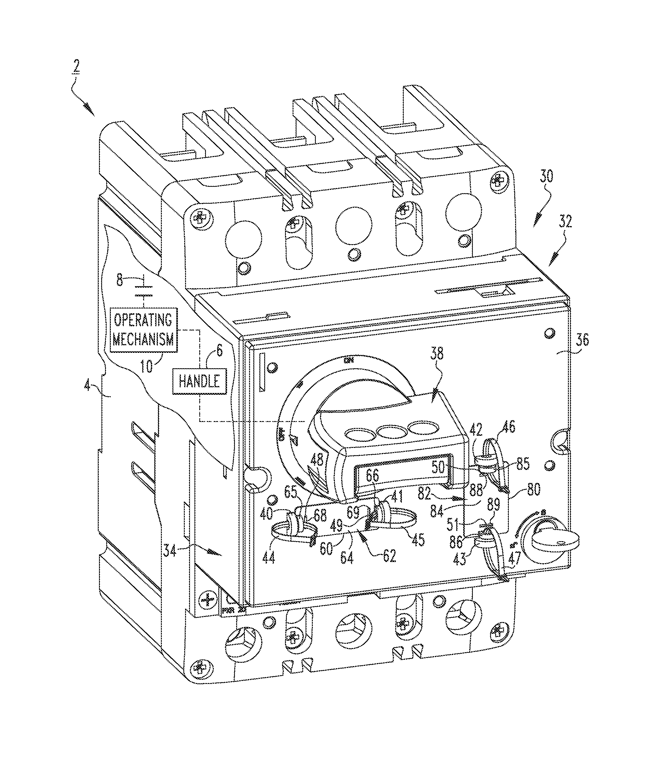
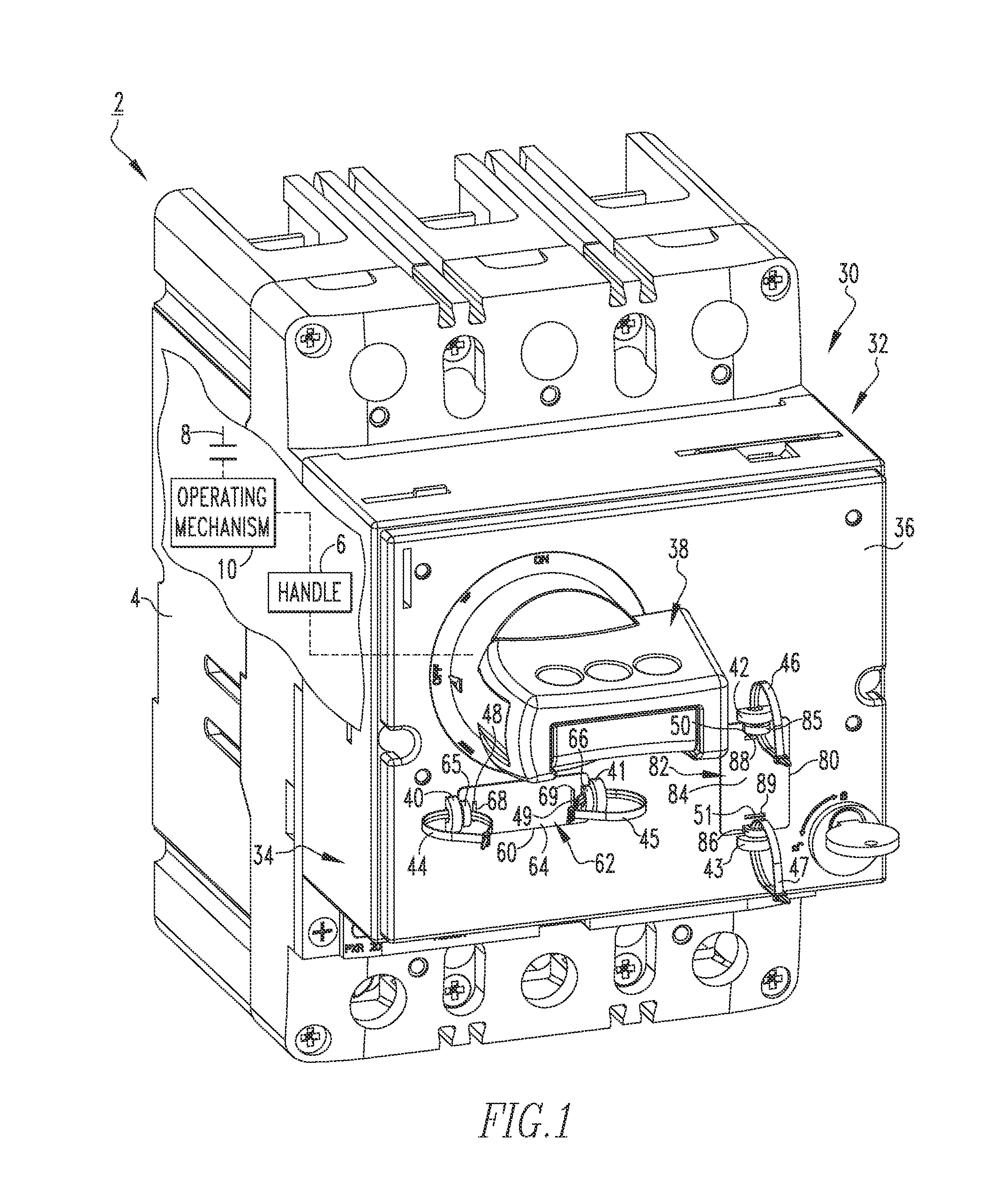
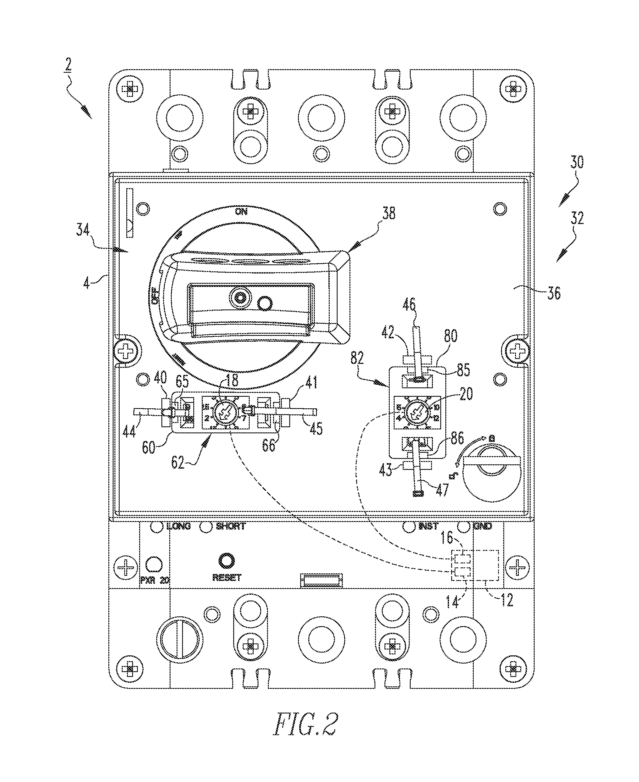
[0028]FIG. 1 shows an electrical switching apparatus (e.g., molded case circuit breaker 2) in accordance with a non-limiting embodim...


PUM


Abstract

An interface assembly is for an electrical switching apparatus. The electrical switching apparatus includes a housing, a first handle partially extending through the housing, separable contacts located within the housing, an operating mechanism to open and close the separable contacts, a main printed circuit board located within the housing, and a number of electrical rating settings associated with the main printed circuit board. Each of the electrical rating settings has a magnitude. The interface assembly includes: a base assembly comprising a base, the base being disposed on the housing, the base having a mounting surface; and a second handle coupled to the mounting surface, the second handle and the first handle being structured to drive each other. The mounting surface has at least one port. The magnitude of a corresponding one of the electrical rating settings is visible through the at least one port.

Description

BACKGROUND[0001]1. Field[0002]The disclosed concept pertains generally to electrical switching apparatus, such as, for example, circuit breakers. The disclosed concept also pertains to interface assemblies and display apparatus for electrical switching apparatus.[0003]2. Background Information[0004]Electrical switching apparatus, are used to protect electrical circuitry from damage due to a trip condition, such as, for example, an overcurrent condition, an overload condition, an undervoltage condition, a relatively high level short circuit or fault condition, a ground fault or arc fault condition. Electronic molded case circuit breakers, for example, include at least one pair of separable contacts which are operated either manually by way of a handle disposed on the outside of the case, or automatically by way of a trip unit in response to the trip condition.[0005]As technology has evolved, additional electronic features have been added to molded case circuit breakers. Many of these...

Claims


Application Information

Patent Timeline
Patent Type & Authority Applications(United States)
IPC IPC(8): H01H71/12
CPCH01H71/128H01H2205/002H01H9/181H01H2071/042H02H3/006H01H2071/006H01H71/126H01H71/06H01H71/74H01H2071/7472H01H2071/7481H01H9/54H01H19/04H01H19/14H05K5/0017
Inventor DEVINE, JACKJANUSEK, MARK A
Owner EATON INTELLIGENT POWER LTD
Learn More