Horse-riding bicycle

Inactive Publication Date: 2016-09-22
KANG IN TAE
View PDF9 Cites 0 Cited by
  • Summary
  • Abstract
  • Description
  • Claims
  • Application Information

AI Technical Summary

Benefits of technology

The present invention provides a bicycle that can be used for both normal driving and horse-riding, allowing for a more exciting and comprehensive workout. The switch between the two modes is simple and convenient for the user, while the structure of the horse-riding mode is simple and cost-effective. The bicycle is designed to have a smooth transition between the two driving modes and provides a better user experience.

Problems solved by technology

However, the driving-mode-switching-type horse-riding bicycle disclosed in Korean Patent Application No. 10-2010-0071166 has a problem in that the structures of a driving-mode-switching main body, a driving-mode-switching guide member, and a pulling device are extremely complicated, resulting in an increase in costs.
In addition, there is a problem in that due to the extremely complicated structures, a switching operation between the normal driving mode and the horse-riding driving mode is not performed smoothly.

Method used


Image

  • Horse-riding bicycle
  • Horse-riding bicycle
  • Horse-riding bicycle

Examples


first embodiment

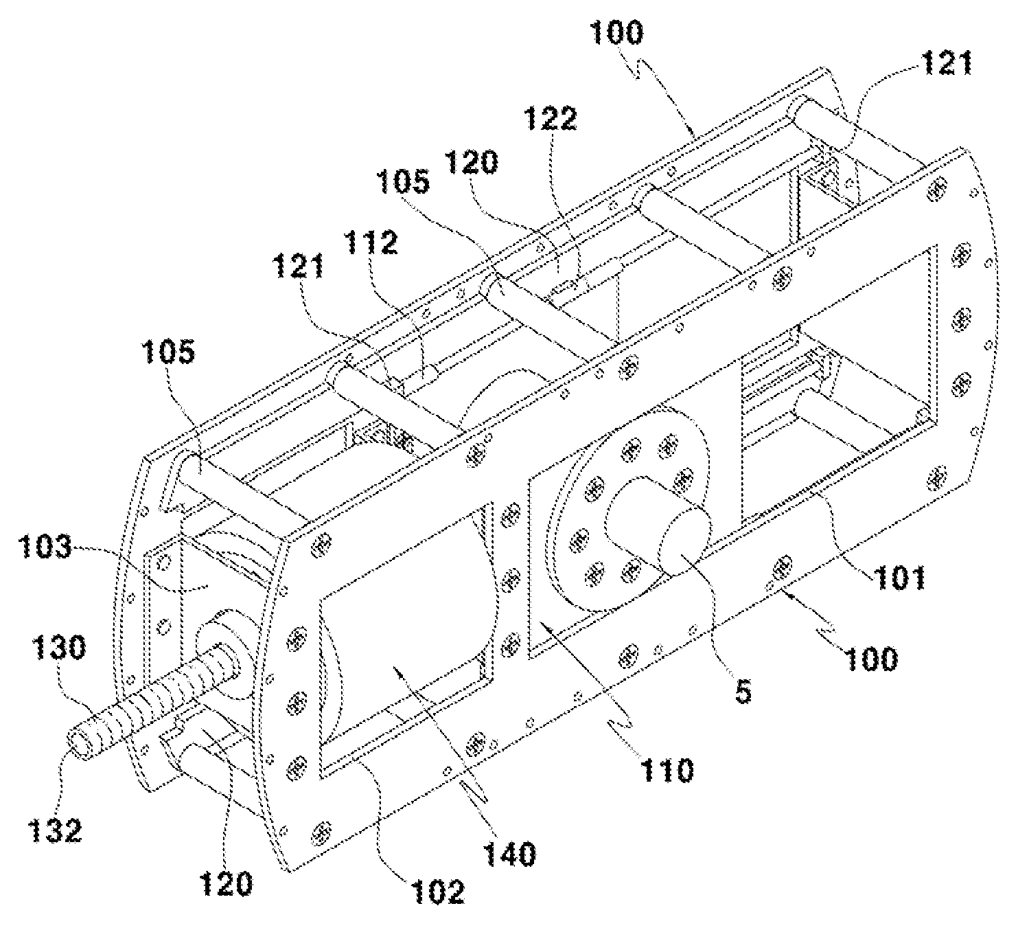
[0054]The details of the whole operational relationship of the horse-riding bicycle according to the present invention configured as described above will be explained below with reference to the appended drawings.

[0055]First, FIGS. 9a and 10a illustrate the normal driving mode state in which the hub 100 and the hub shaft 5 are concentrically disposed. In this state, the hub 100 maintains a concentric state in relation to the hub shaft 5. Furthermore, when the bicycle 1 is driven in this state, the left and right fixing rings 150a and 150b does not interfere with the movement roller 140 rotating with the hub 100. As a result, the hub 100 does not swing and rotates in a state where the hub 100 maintains the normal driving mode in concentric with the hub shaft 5.

[0056]In the normal driving mode, the movement roller 140 is separate from the pad 151a of the left fixing ring 150a and the pad 151b of the right fixing ring 150b, as illustrated in FIGS. 9a and 10a. As a result, during drivin...

second embodiment

[0080]The details of the whole operational relationship of the horse-riding bicycle according to the present invention configured as described above will be explained below with reference to the appended drawings.

[0081]First, FIG. 19a illustrates the normal driving mode state in which the hub 200 and the hub shaft 5 are concentrically disposed. In this state, the hub 200 maintains a concentric state in relation to the hub shaft 5. Furthermore, when the bicycle 1 is driven in this state, the motor 230 which rotates with the hub 200 is not driven. As a result, the hub 200 does not swing and rotates in a state where the hub 200 maintains the normal driving mode in concentric with the hub shaft 5.

[0082]Next, when a user switches a mode of the switching member 270 to the horse-riding driving mode in the normal driving mode so as to switch the driving mode to the horse-riding driving mode, the shaft 231 of the motor 230 is driven in the reverse direction in which the nut 202 moves outward...


PUM


Abstract

Provided is a horse-riding bicycle in which a horse-riding effect is obtained by performing both normal driving and horse-riding driving (swinging driving), a user is allowed to simply switch a driving mode between a normal driving mode and a horse-riding driving mode, and a horse-riding driving structure is improved to have a simple structure so that a reduction in costs is achieved and, further, a switching operation between the normal driving mode and the horse-riding driving mode is smoothly performed.

Description

CROSS-REFERENCE(S) TO RELATED APPLICATION[0001]This application claims priority of Korean Patent Application No. 10-2015-0037617, filed on Mar. 18, 2015, in the Korean Intellectual Property Office, which is hereby incorporated by reference in its entirety.BACKGROUND OF THE INVENTION[0002]1. Field of the Invention[0003]The present invention relates to a horse-riding bicycle in which a horse-riding effect can be obtained by performing both normal driving and horse-riding driving (swinging driving), a user can simply switch a driving mode between a normal driving mode and a horse-riding driving mode, and a horse-riding driving structure is improved to have a simple structure so that a reduction in costs can be achieved and, further, a switching operation between the normal driving mode and the horse-riding driving mode is smoothly performed.[0004]2. Description of the Related Art[0005]Generally, horse-riding bicycles having various structures have been applied. Korean Patent Applicatio...

Claims


Application Information

Patent Timeline
IPC IPC(8): B62K13/00B62K3/02B62K23/02B62K21/12
CPCB62K13/00B62K23/02B62K3/02B62K21/12B62K3/00B62K17/00B62J43/13B62J43/28B62K23/04B62K25/02B62M9/085A63G19/04
InventorKANG, IN TAE
OwnerKANG IN TAE