Slidable cabinet pullout apparatus and method of use

a pull-out cabinet and pull-out technology, applied in the field of sliding pull-out cabinets, can solve the problems of inability to adjust the frontal screen easily, the device does not provide a self-centering mounting base or adjustable face plate, and the rear area of the simple shelving suffers from the drawback of unusable rear areas

Active Publication Date: 2016-09-29
HARDWARE RESOURCES
View PDF11 Cites 9 Cited by
  • Summary
  • Abstract
  • Description
  • Claims
  • Application Information

AI Technical Summary

Benefits of technology

[0010]In a preferred embodiment, a decorative face plate is attached to the front panel of the drawer box with an adjustable face plate mounting system. A slotted, rectangular bracket providing horizontal and vertical adjustment capability is connected to the face plate. A standoff assembly slidably engages the slot in the bracket and is fixed to the front panel. In an alternate embodiment, a T-nut is fixedly engaged with the front panel and an adjustable set screw is threadably engaged with the T-nut. The adjustable set screw abuts the slotted bracket to provide depth adjustment capability.

Problems solved by technology

However, simple shelving suffers from the drawback of unusable rear areas in corners where items are difficult to see and reach.
The device does not provide a self centering mounting base or an adjustable face plate.
The frontal screen is not easily adjustable.
The drawer does not provide an adjustable face plate.
Despite the advantages of the prior art, a major drawback has been that the pullout devices disclosed are not easily installed or adjusted.
The prior art fails to disclose or suggest a pullout cabinet device that is easily and accurately mounted and which is easily adjustable to accommodate alignment with adjacent cabinets.

Method used


Image

  • Slidable cabinet pullout apparatus and method of use
  • Slidable cabinet pullout apparatus and method of use
  • Slidable cabinet pullout apparatus and method of use

Examples


Embodiment Construction

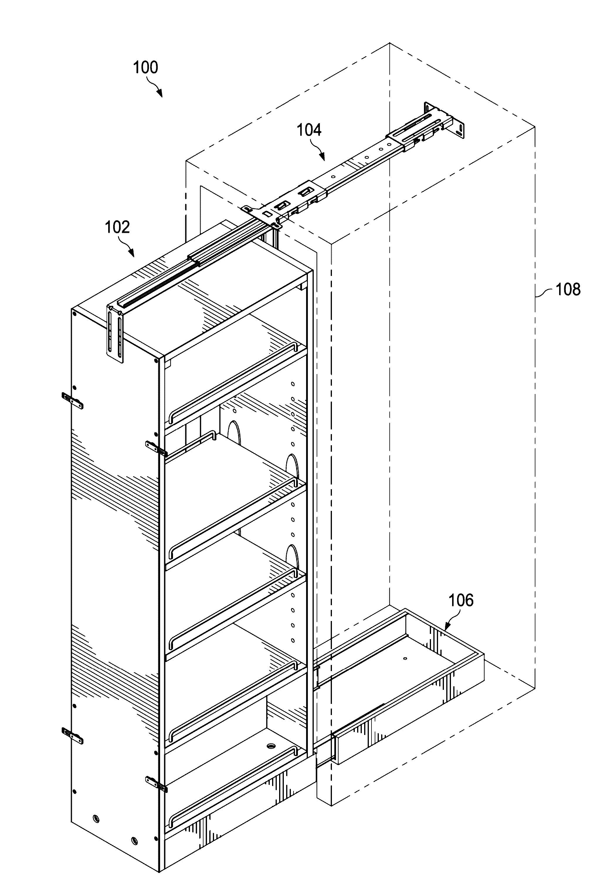
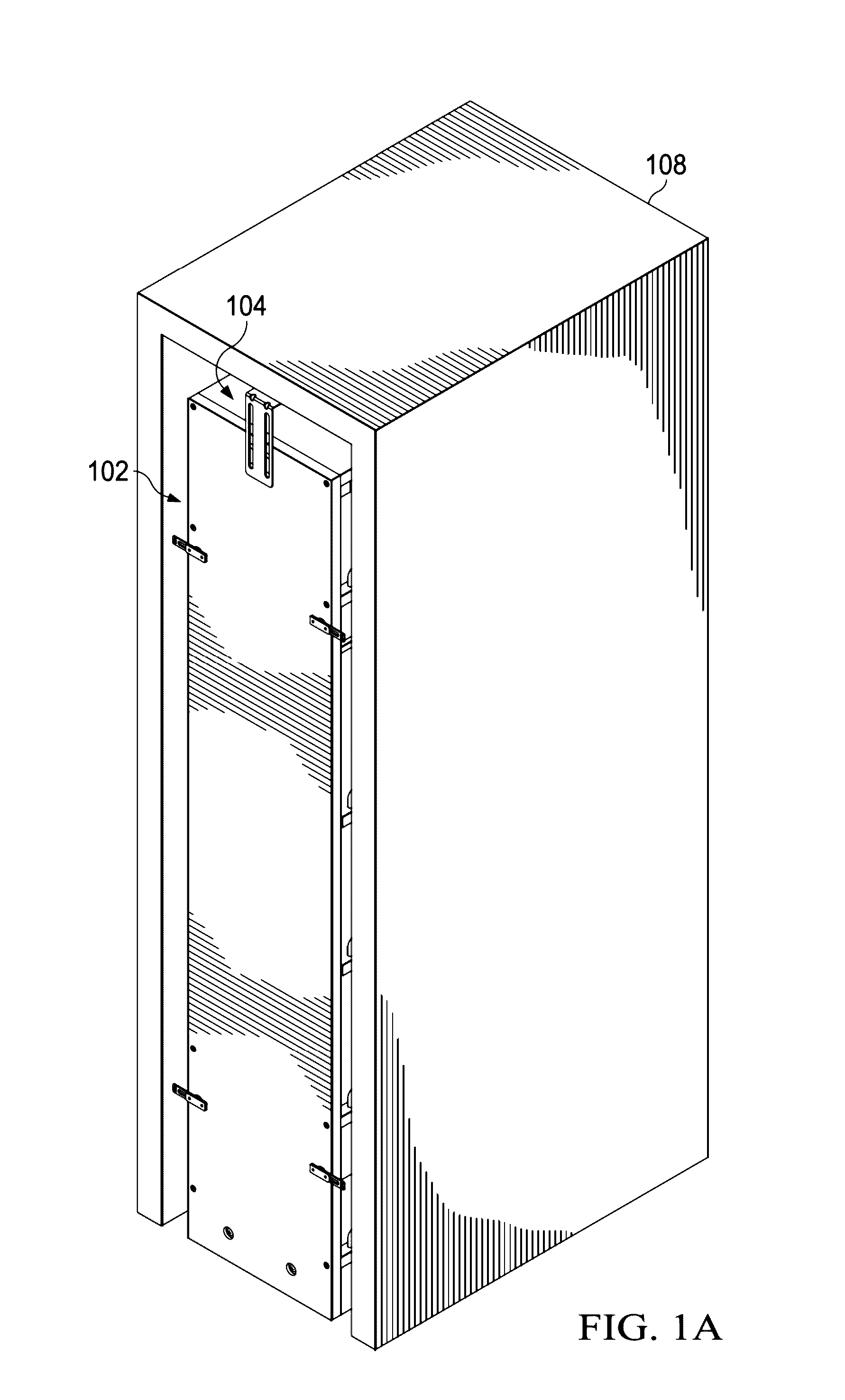
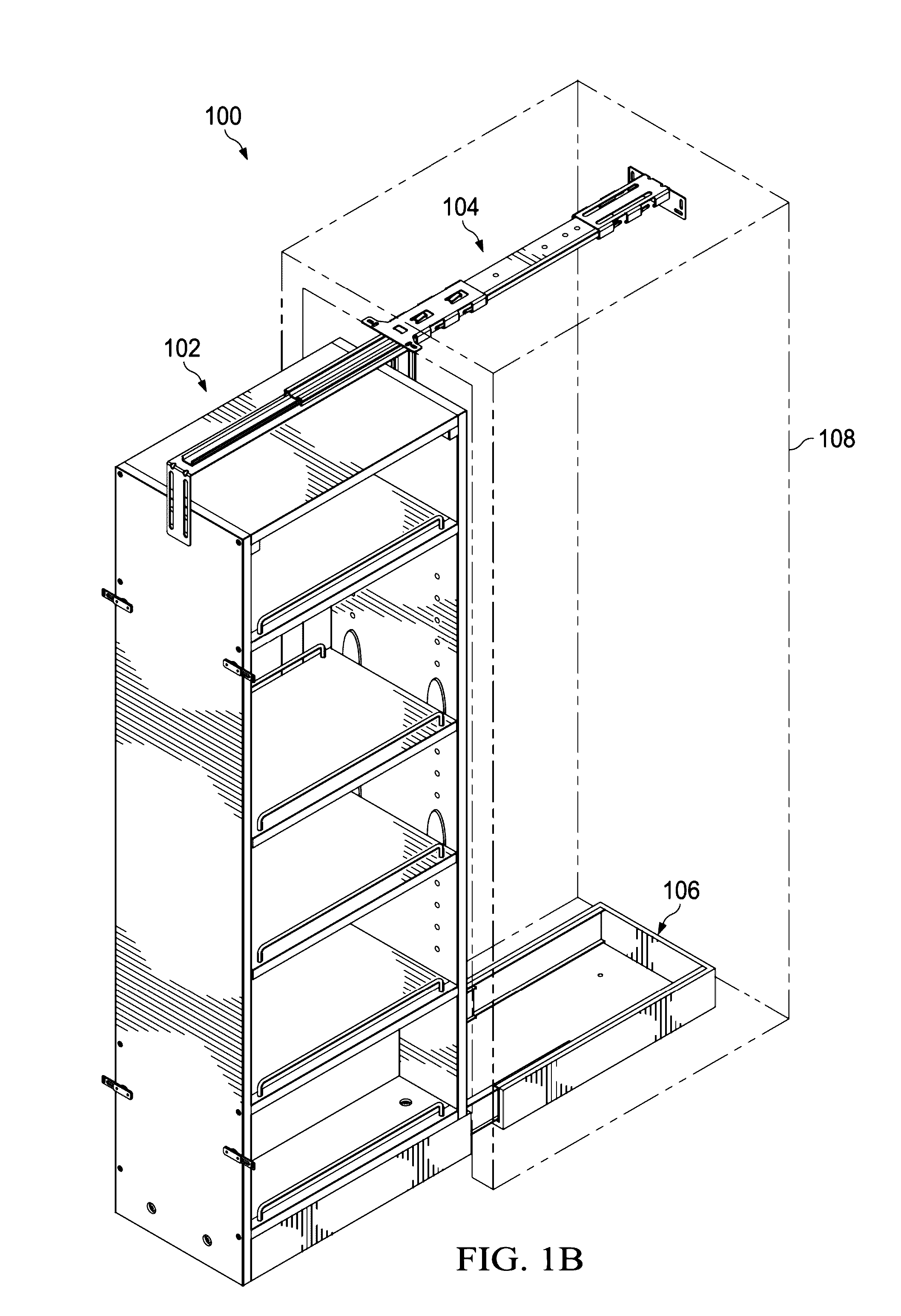
[0048]Referring to FIGS. 1A and 1B, pantry pullout apparatus 100 comprises drawer box 102 connected to top slide assembly 104 and base slide box 106. Drawer box 102 is connected to and slidable within base slide box 106. Top slide assembly 104 and base slide box 106 are mounted to cabinet carcass 108. Drawer box 102 is slidable between a “stowed” position within the cabinet carcass (FIG. 1A) and a “deployed” position (FIG. 1B). In the stowed position, the drawer box and its contents are hidden from view. In the deployed position, the contents stored on the shelves are visible and capable of being easily reached from either side.

[0049]Referring to FIG. 2, drawer box 102 is generally rectangular having a closed top and bottom with open sides. Drawer box 102 comprises front panel 202 connected to rear panel 211 by top panel 214. Fixed shelves 203, 205, and 206 are rigidly connected to and generally perpendicular with both front panel 202 and rear panel 211. A plurality of adjustable sh...


PUM


Abstract

Disclosed is a pullout apparatus having side access and designed for simple, adjustable, and accurate installation within a pre-existing cabinet space. The apparatus, slidably mounted within the cabinet space, comprises a top slide assembly mounted to a cabinet carcass and a drawer box. The drawer box is automatically centered on a base slide box. The base slide box is comprised of a slotted template slidingly engaged with a frame, where the frame is mounted to the cabinet carcass. Slide rail assemblies connect the slotted template to the frame. A pin block on the underside of a fixed shelf of the drawer box automatically centers the drawer box on the slotted template. A face plate adjustment mechanism provides for three dimensional alignment of the face plate with surrounding cabinets. An alternate embodiment comprises a mounting bracket providing three dimensional adjustability of the upper drawer slide.

Description

CROSS-REFERENCE TO RELATED APPLICATIONS[0001]This application is a Continuation-In-Part of application Ser. No. 14 / 797,643, filed Jul. 13, 2015, which claims the benefit of U.S. Provisional Patent Application No. 62 / 076,602 filed on Nov. 7, 2014. Each patent application identified above is incorporated herein by reference in its entirety to provide continuity of disclosure.FIELD OF THE DISCLOSURE[0002]The present disclosure relates to cabinet structure, cabinets, and drawers. In particular, the disclosure relates to a slidable pullout cabinet with an adjustable face plate and an adjustable mounting bracket.BACKGROUND OF THE DISCLOSURE[0003]Modern kitchens place a premium on sufficient usage of storage for utensils, dry goods, and can goods. In the past, the traditional kitchen includes simple shelving to accommodate these items. However, simple shelving suffers from the drawback of unusable rear areas in corners where items are difficult to see and reach.[0004]In an effort to overco...

Claims


Application Information

Patent Timeline
Patent Type & Authority Applications(United States)
IPC IPC(8): A47B88/04A47B96/02A47B88/10A47B88/493
CPCA47B88/0407A47B88/0485A47B88/10A47B2210/0054A47B2210/0035A47B2210/0062A47B2210/0056A47B96/02A47B88/407A47B88/42A47B88/43A47B88/493A47B88/57A47B88/956A47B2088/422A47B2210/0032
Inventor CHEN, ALAN
Owner HARDWARE RESOURCES
Why Eureka
Try Eureka