Method for calibrating a linearizer and linearized electronic component

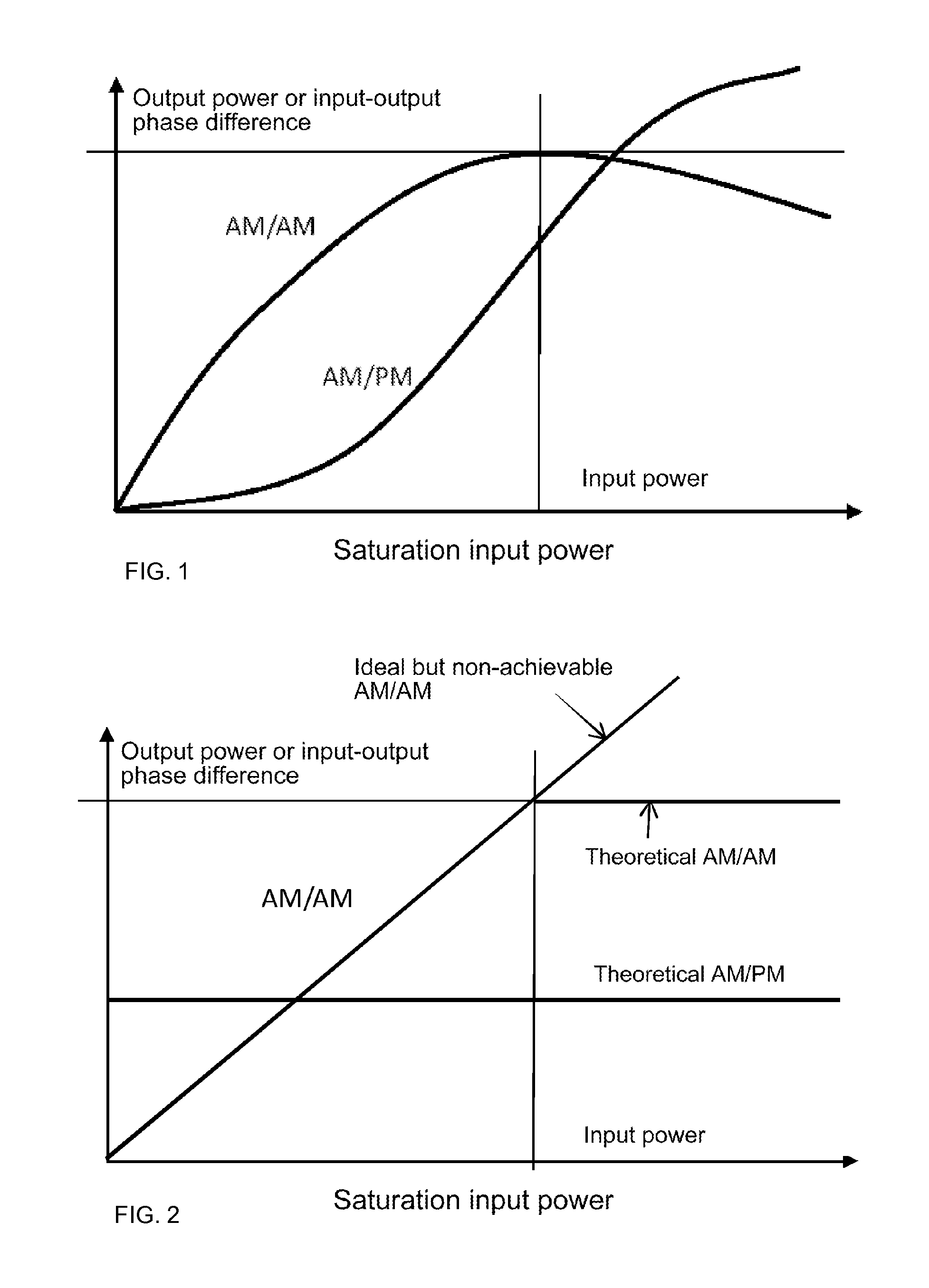
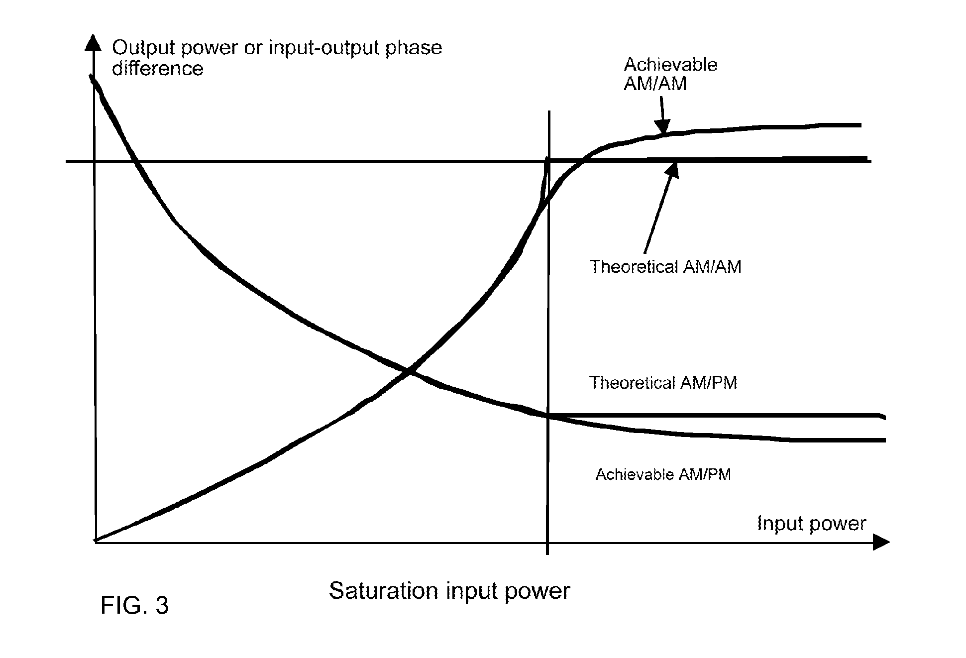
a linearizer and electronic component technology, applied in the direction of modulation, transmission, transmitter/receiver shaping network, etc., can solve the problem of inability to obtain linear am/am curves extending beyond the saturation power of amplifiers, and the theoretical am/am curve of linearizers is not accurately physically achievabl

Active Publication Date: 2015-03-10
CENT NAT DETUD SPATIALES (CNES)
View PDF18 Cites 4 Cited by
  • Summary
  • Abstract
  • Description
  • Claims
  • Application Information

AI Technical Summary

Benefits of technology

[0026]The invention proposes a method for linearization by predistortion which makes it possible to adjust the setting of the linearizer located upstream of an electronic component to be linearized during operation of the latter in order to take account of equipment drift or in the event of a change in the environment, this being achieved without necessarily directly measuring the phase difference of the output signal relative to the input or demodulating the output signal.
[0036]Steps c1) to c2) are advantageously carried out for a plurality of power levels of the bifrequency test signal, which makes it possible to reduce the dissimilarity of the input and output spectra over a range of input powers extending for example up to the saturation input power or up to the maximum service power of the electronic component. The variable indicative of dissimilarity may then be a function (inter alia) of the relative power levels of the second and third output signal components.
[0041]The method according to the invention makes it possible, for example, to set (recalibrate) an amplifier linearizer on a satellite in orbit in order to correct the consequences of aging, of a change in broadcasting frequency and / or a change in environmental conditions.
[0047]Steps c5) to c7) are preferably carried out for a plurality of power levels of the monofrequency test signal, which makes it possible to construct the AM / AM curve of the linearized electronic component.

Problems solved by technology

For example, it is difficult to provide a transmission chain with linear behavior over a wide bandwidth and a large signal power range.
It will be noted that it is not possible to obtain a linear AM / AM curve extending beyond the saturation power of the amplifier.
The theoretical AM / AM curve of the linearizer is not accurately physically achievable up to saturation.
This variant has the disadvantage that variation in environmental conditions and drift over time of amplifier and linearizer characteristics may reduce linearization quality.once and for all at the start of operation, but for a range of parameters such as temperature, frequency, gain, etc. in order to obtain a set of AM / AM and AM / PM curves, from which is selected the one which is best suited to the environmental conditions measured during operation of the linearized amplifier.periodically, by one or more feedback loops in order to follow the variations, assumed to take place more slowly, in the environment and equipment characteristics.permanently by one or more feedback loops.

Method used


Image

  • Method for calibrating a linearizer and linearized electronic component
  • Method for calibrating a linearizer and linearized electronic component
  • Method for calibrating a linearizer and linearized electronic component

Examples


Embodiment Construction

[0067]FIGS. 1 to 3 have already been discussed in the “Background” section.

Linearization of an Amplifier

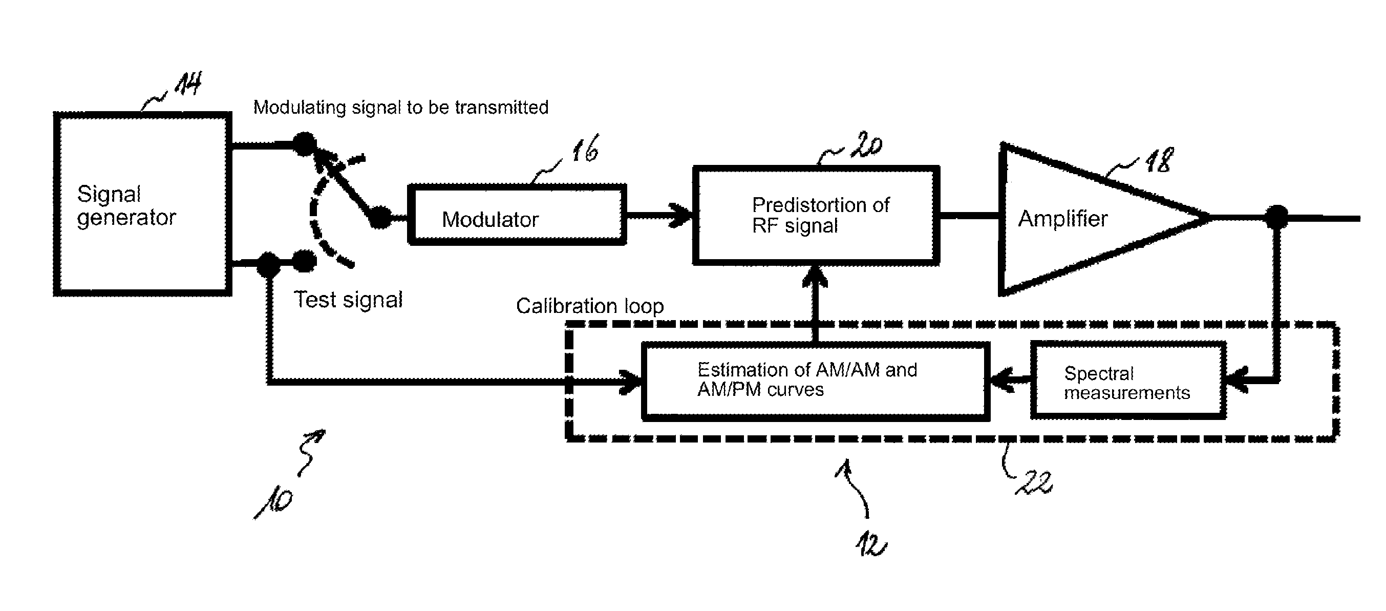
[0068]A transmission chain 10 comprising a linearized amplifier device 12 according to a first and a second preferred embodiment of the invention is shown schematically in FIG. 4 and FIG. 5 respectively. The transmission chain 10 comprises a signal generator 14 which supplies a baseband signal (modulating signal). A modulator 16 modulates the modulating signal on a carrier. The resultant RF signal is amplified by a power amplifier 18. A predistortion linearizer 20 is located upstream of the amplifier 18 so as at least in part to compensate the nonlinear distortion added to the signal by the amplifier 18. According to the embodiment of the invention shown in FIG. 4, the predistortion linearizer 20 is placed downstream of the modulator 16 and therefore acts on the RF signal to be amplified. In FIG. 5, the predistortion linearizer 20 is placed upstream of the modulator 16 and acts on...


PUM


Abstract

Method for calibrating a linearizer and linearized electronic component the method comprises predistortion, in a predistortion linearizer, of a signal upstream of an electronic component to compensate nonlinear distortion. Determining predistortion setting parameters comprises applying a bifrequency test signal to the component and measuring the relative amplitudes of the lines at the output of the component. A variable indicative of the magnitude |Kp| of the AM / PM conversion coefficient of the component is calculated on the basis of these measurements. The predistortion setting parameters are adjusted so as to minimize |Kp|. The method may in particular be implemented in a linearized amplifier device and in an amplifier test bench.

Description

FIELD OF THE INVENTION[0001]The invention relates in general to the compensation of nonlinear distortion. In particular, the invention is directed at linearization by predistortion, in particular at a method for calibrating a predistortion linearizer. Another aspect of the invention relates to a device which implements such a method.BACKGROUND[0002]The components of an analog transmission chain all exhibit a greater or lesser degree of nonlinear behavior depending on the specific features of the transmitted signal. For example, it is difficult to provide a transmission chain with linear behavior over a wide bandwidth and a large signal power range.[0003]Typical examples of sources of nonlinear distortion are digital / analog or analog / digital converters and amplifiers, in particular power amplifiers. This is because the latter operate as close as possible to saturation in order to maximize the added power efficiency and operating an amplifier close to its saturation point introduces n...

Claims


Application Information

Patent Timeline
Patent Type & Authority Patents(United States)
IPC IPC(8): H04K1/02H04L25/03H04L25/49H03F1/32H04B1/04
CPCH04B1/0475H03F1/3247H03F1/3288H04B2001/0425H03F1/3241
Inventor SOMBRIN, JACQUESGIRAUD, XAVIERGUERIN, ALEXANDRELESTHIEVENT, GUYMILLERIOUX, JEAN-PIERREDEPLANCQ, XAVIER
Owner CENT NAT DETUD SPATIALES (CNES)
Why Eureka
Try Eureka