Device for securing posts together

a technology for securing posts and bundles, applied in the direction of package recycling, rod connections, packaging goods types, etc., can solve the problems of difficult storage and transportation, difficult stacking of bundles for storage or transportation, and difficulty in unpacking bundles, etc., to achieve tighter packing density, simplify storage and transportation of post bundles, and increase the effect of packing density

Active Publication Date: 2016-09-29
INFRABUILD WIRE PTY LTD
View PDF20 Cites 0 Cited by
  • Summary
  • Abstract
  • Description
  • Claims
  • Application Information

AI Technical Summary

Benefits of technology

[0036]In one form, the posts may be positioned so that at least one of their respective ends are aligned with the respective ends of one or more of the other posts. This can simplify storage and transport of the post bundles.
[0037]In one form, when the posts are of a Y- or T-shaped profile, the posts may be arranged such that the profiles of adjacent posts are inverted. In this regard, and in one example where a bundle of ten posts is being formed, a series of Y-posts may be aligned by first placing five Y-posts so that their so-called wings are arranged end to end on a surface, such as the ground. Four Y-posts can then be arranged such that their stalks are positioned on the wings of the five adjacent posts, with their wings resting on the stalks of the five adjacent posts, thereby inverting the profiles of adjacent posts. A final post can be positioned on an outer post in a similar manner. When the apertures in the post are located closer to a stem of the post, such as when a slot is employed as the aperture, i.e. when compared to a traditional post having a round / circular hole, such a bundle arrangement can provide an increased packing density of approximately forty percent, as adjacent posts can have their profile inverted whilst still allowing the slots in adjacent posts to be aligned. This tighter packing density can also minimise the amount of relative movement between the posts.
[0038]In one form, the first end of the device may be configured such that a portion of the first end deflects to allow the first end to be passed through an aperture. The first end can deflect back, once it has been passed through the aperture. This can prevent the first end from being withdrawn through the aperture.
[0039]In one form, when the post apertures are shaped to have an elongate axis (such as a slot), the first end may be configured such that, by altering the orientation of the device, the first end can be prevented from being withdrawn through the aperture. For example, the first end can be aligned with the long axis of the slot when the first end is being passed therethrough. Once all of the posts have been positioned on the device, the first end and / or device can be rotated (e.g. by ninety degrees), so that the first end is no longer aligned with the long axis of the slot thereby preventing it from being withdrawn therethrough.

Problems solved by technology

Fence posts and the like, due to their shape, are often difficult to store and transport.
However, when this bundle is being stored or transported the posts will tend to move along the wire.
This can cause kinks along the length of the wire which can make unpacking of the bundle quite difficult and time consuming, requiring the aid of good tools and wire cutters to enable the kinked wire to be removed from between the posts.
Further, movement of the posts along the wire forms awkward bundle shapes which can make stacking of the bundles for storage or transport difficult, due to the resulting inconsistent trapezoidal shape.
The bundles can also look untidy, as there is no uniformity between the bundles, and there are excessive amounts of the thin ductile wire that is used for tying off the bundles extending out and beyond the bundles.
Other storage and transport solutions have been proposed, such as crates or trays, but these options are generally quite bulky and heavy, leading to an unnecessary increase in transport costs due to the increased weight and reduced number of posts able to be transported.
However, once one end cap has been removed, and / or a single post has been removed from the bundle, the remaining posts become looser in the bundle, and one post may work its way out of the capping unless the cap is bolted back on, which may not be easy to achieve.
However, if the first end and / or device is rotated (e.g. by ninety degrees), the first end is no longer aligned with the long axis of the slot.
In this regard, whilst one form of configurable first end may be able to be passed through one type of aperture, it may not necessarily be able to be passed, unhindered or not, through another type of aperture.

Method used


Image

  • Device for securing posts together
  • Device for securing posts together
  • Device for securing posts together

Examples


example 1

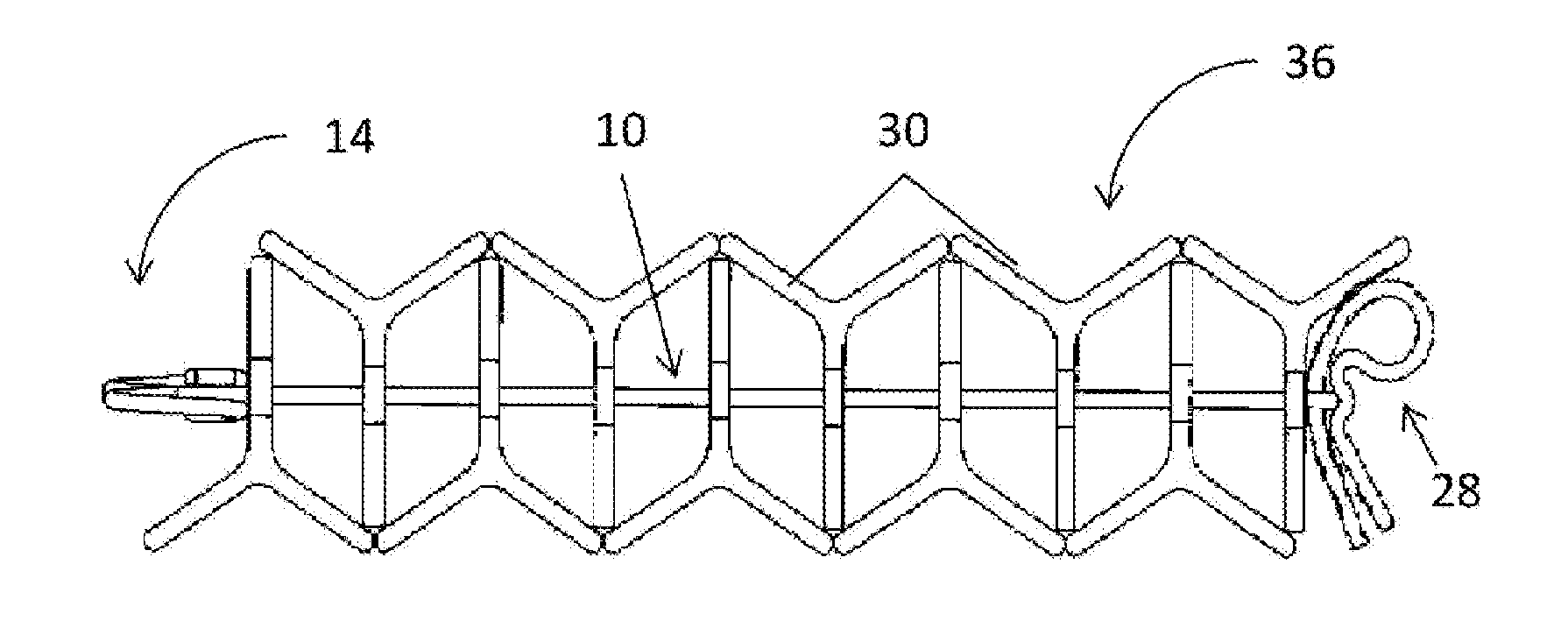
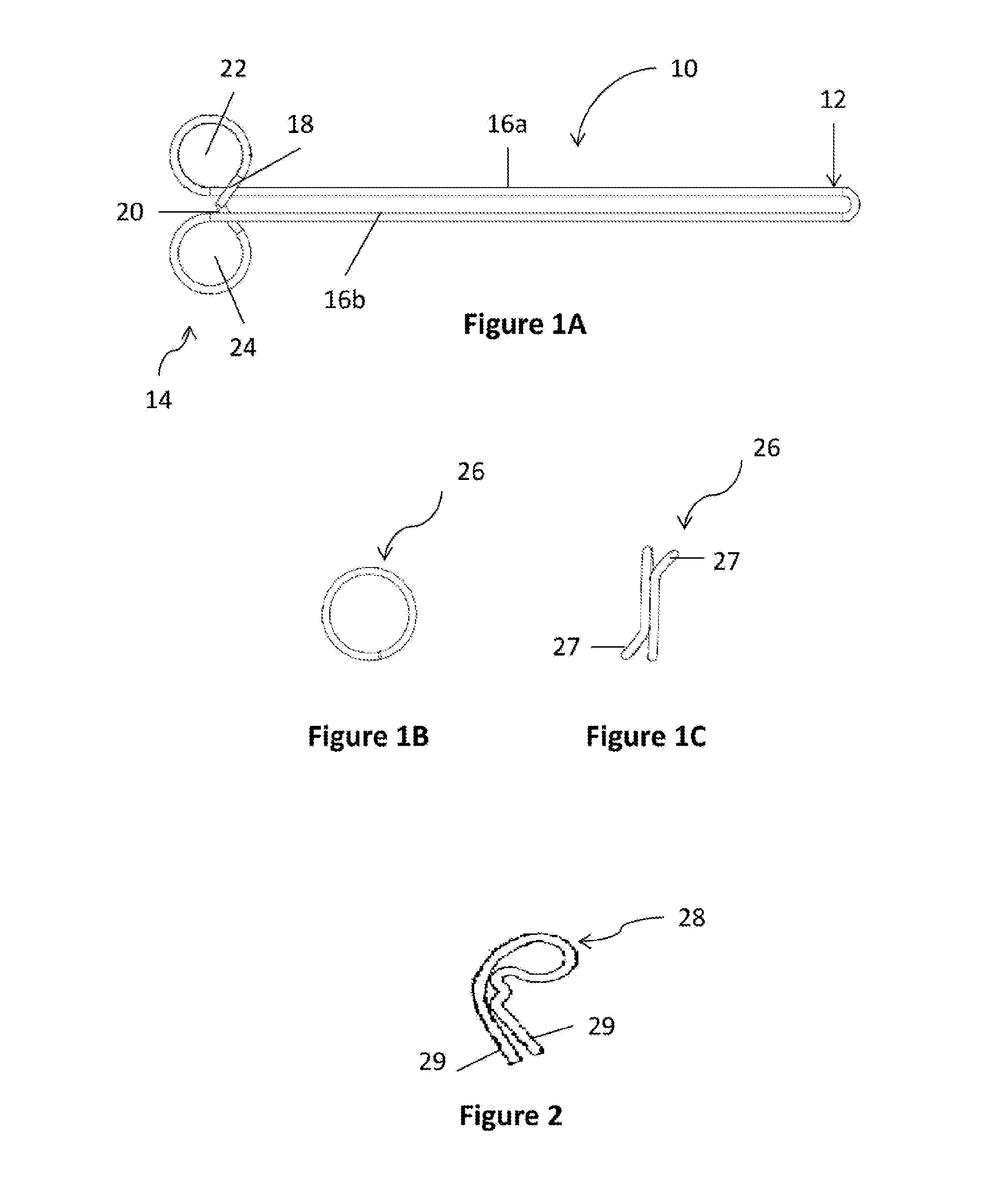
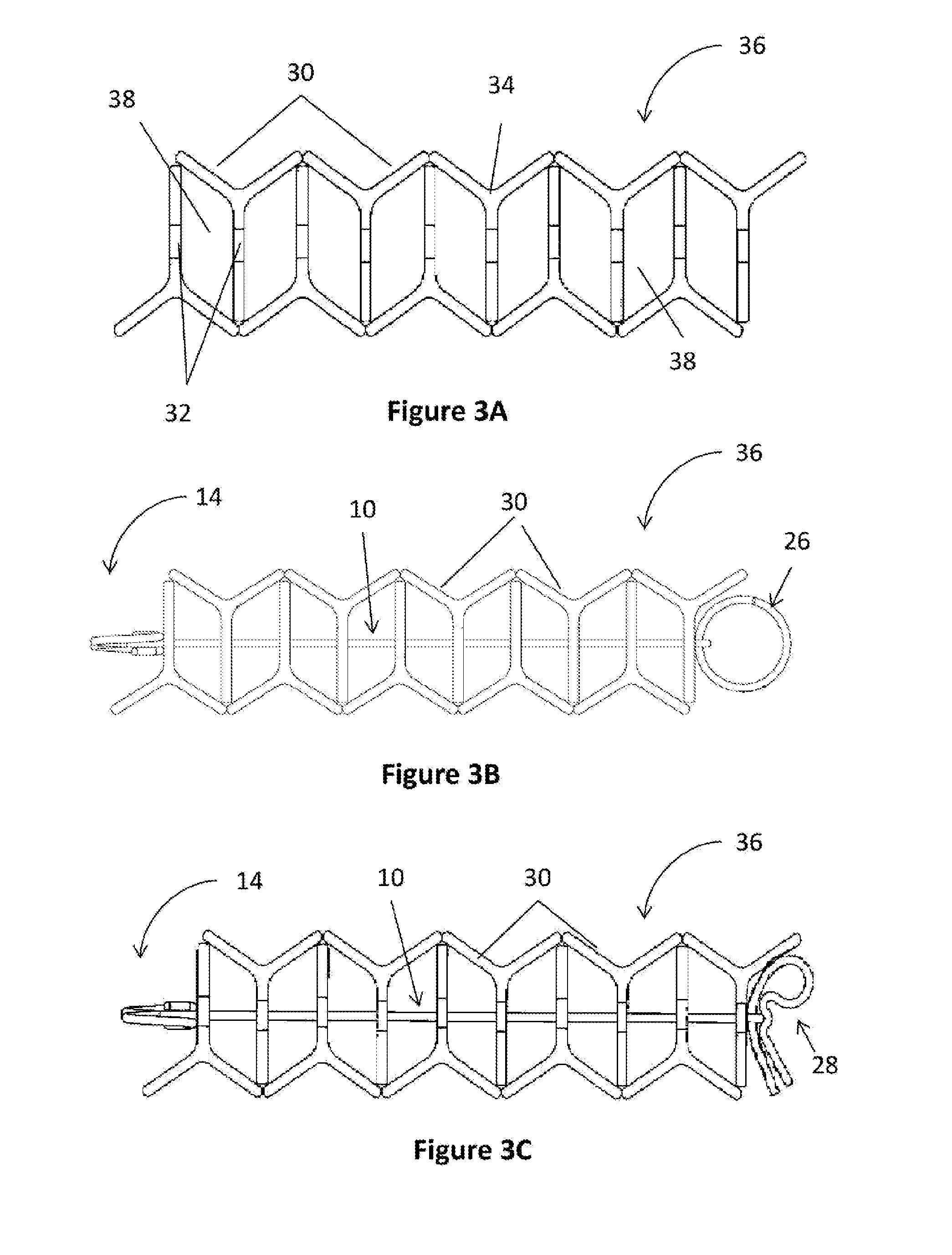
[0108]A small bundle of ten Y-posts was made, that was to be used in the creation of a larger stack of posts for storage or transport, using ten Y-posts together with two spikes 10 and two split rings 26. Each of the posts had seven apertures, in the form of elongate slots, in their stalks.

[0109]Five Y-posts 30 were positioned on a bench so that the pointed ends were all at the same end, the wings were located on the bench, and so that an edge of one of the wings (i.e. one of the minor flanges) touched the edge of a wing of an adjacent post. This positioned the first five Y-posts so that their stalks extended perpendicularly to the bench, and approximately parallel to each other stalk.

[0110]Four Y-posts were then arranged such that, with their pointed ends at the same end of the bench as the already positioned Y-posts, a distal longitudinal edge of their stalks were positioned on the joint formed between the wings of adjacent posts. In this regard, the profile of these four Y-posts ...

example 2

[0114]A bundle of ten Y-posts were to be transported in the back of a vehicle for use in mending a fence line having a number of broken posts. A handle 500 was employed to move the bundle formed in Example 1.

[0115]The foot 508 and leg 504, and the foot 510 and leg 506, of the handle 500 were inserted into the space / cavity 38 formed between the first and second adjacent posts and the ninth and tenth adjacent posts, respectively, in the bundle, by holding the gripping portion 502 of the handle and aligning the legs 504, 506 with the cavities.

[0116]The feet 508, 510 and legs 504, 506 were then inserted into the respective cavities. The feet 508, 510 contacted the elongate portion 16 of the spike 10, which caused the feet 508, 510 to deflect at ankles 512, 514 and be urged towards the legs 504, 506. As the legs 504, 506 continued to be inserted into the cavities, the feet 508, 510 continued to be deflected towards the legs 504, 506 until they had passed the elongate portion 16 of spike ...

example 3

[0121]One thousand six hundred posts were to be stored for future sale as bundles of twenty posts. Each of the posts had eleven apertures, in the form of elongate slots, in their stalks. Three spikes 210, as shown in FIG. 5, were used to secure each bundle of twenty posts, and a handle 700, as shown in FIG. 10, was also used to allow the bundles to be easily moved.

[0122]The twenty posts were aligned in similar manner to the ten posts described in Example 1, with the profile of each post being inverted with respect to its adjacent post.

[0123]The first end 212 of a first spike 210 was inserted through aligned apertures at one end of the posts. As the first end 212 passed through an aperture, end 220 of the hooked leg portion 218 contacted an edge of the aperture causing the hooked leg portion 218 to deflect towards the elongate portion 216, allowing it to pass through the aperture. Once it had passed through the aperture, the hooked leg portion 218 is angled such that its end 220 enga...


PUM


Abstract

A device for securing two or more posts together is disclosed. The device comprises a first end that can be passed through the post apertures, that is also configurable to prevent the first end from being withdrawn through the apertures, and a second end adapted to prevent the second end from passing through the apertures. The device may be reusable or non-reusable. A handle for use in moving a bundle of two or more posts is also disclosed. The bundle may have been formed with the device, or in another manner. The device and handle may be separate components or integrally formed. Systems and methods employing the device and/or handle are also disclosed.

Description

TECHNICAL FIELD[0001]A device, method and system are disclosed for securing two or more posts together. A handle and system for use in moving a bundle of two or more posts are also disclosed. It should be appreciated that the device, method, handle and system are not limited to post applications, but may be employed in the securing and moving of other elongate objects.BACKGROUND ART[0002]Fence posts and the like, due to their shape, are often difficult to store and transport. A thin piece of wire can be used to tie a small bundle of posts together. Each post forming part of the bundle is threaded onto the piece of wire (i.e. the wire is threaded through a hole in the post) and the wire is then tied off at the outer posts, thereby forming the small bundle of posts. However, when this bundle is being stored or transported the posts will tend to move along the wire. This can cause kinks along the length of the wire which can make unpacking of the bundle quite difficult and time consumi...

Claims


Application Information

Patent Timeline
Patent Type & Authority Applications(United States)
IPC IPC(8): B65D67/02B65B27/10F16B7/00
CPCB65D67/02E04H17/00B65B27/10F16B7/00B65B19/34F16B7/0433E04H17/261Y02W30/80
Inventor WHITE, MARK
Owner INFRABUILD WIRE PTY LTD
Why Eureka
Try Eureka