
Aerodynamically Actuated Thrust Vectoring Devices

a thrust vectoring and actuator technology, applied in vertical landing/take-off aircraft, aircraft navigation control, transportation and packaging, etc., can solve the problem that the prior art solutions for thrust vectoring systems have not resolved the need for an approach to perform one or more of the above actions

Active Publication Date: 2016-10-06
NASA
View PDF0 Cites 69 Cited by
  • Summary
  • Abstract
  • Description
  • Claims
  • Application Information

AI Technical Summary

Benefits of technology

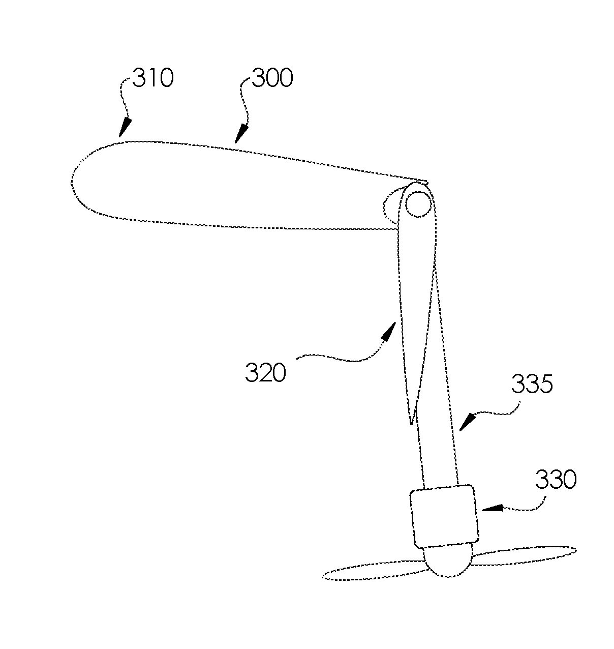
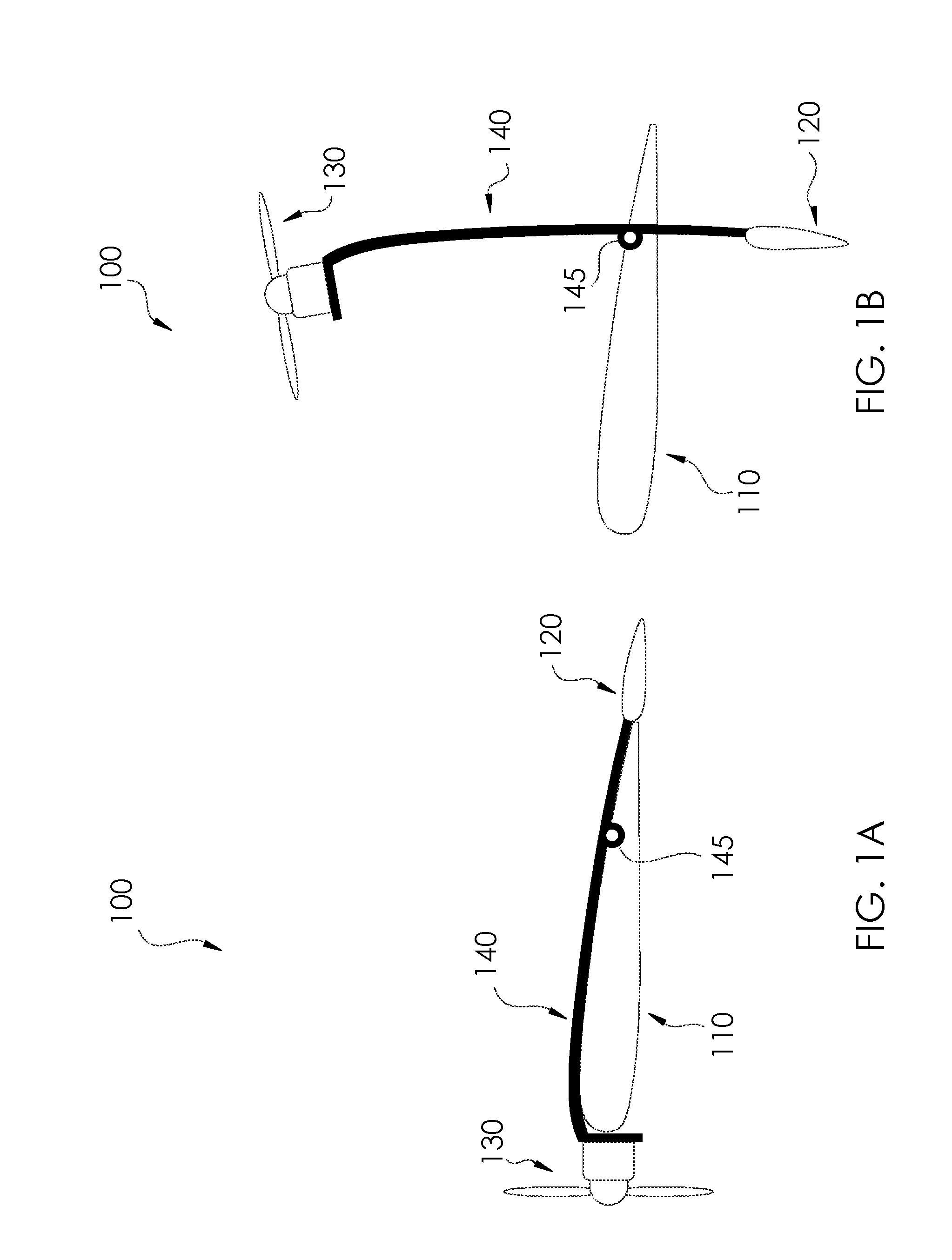
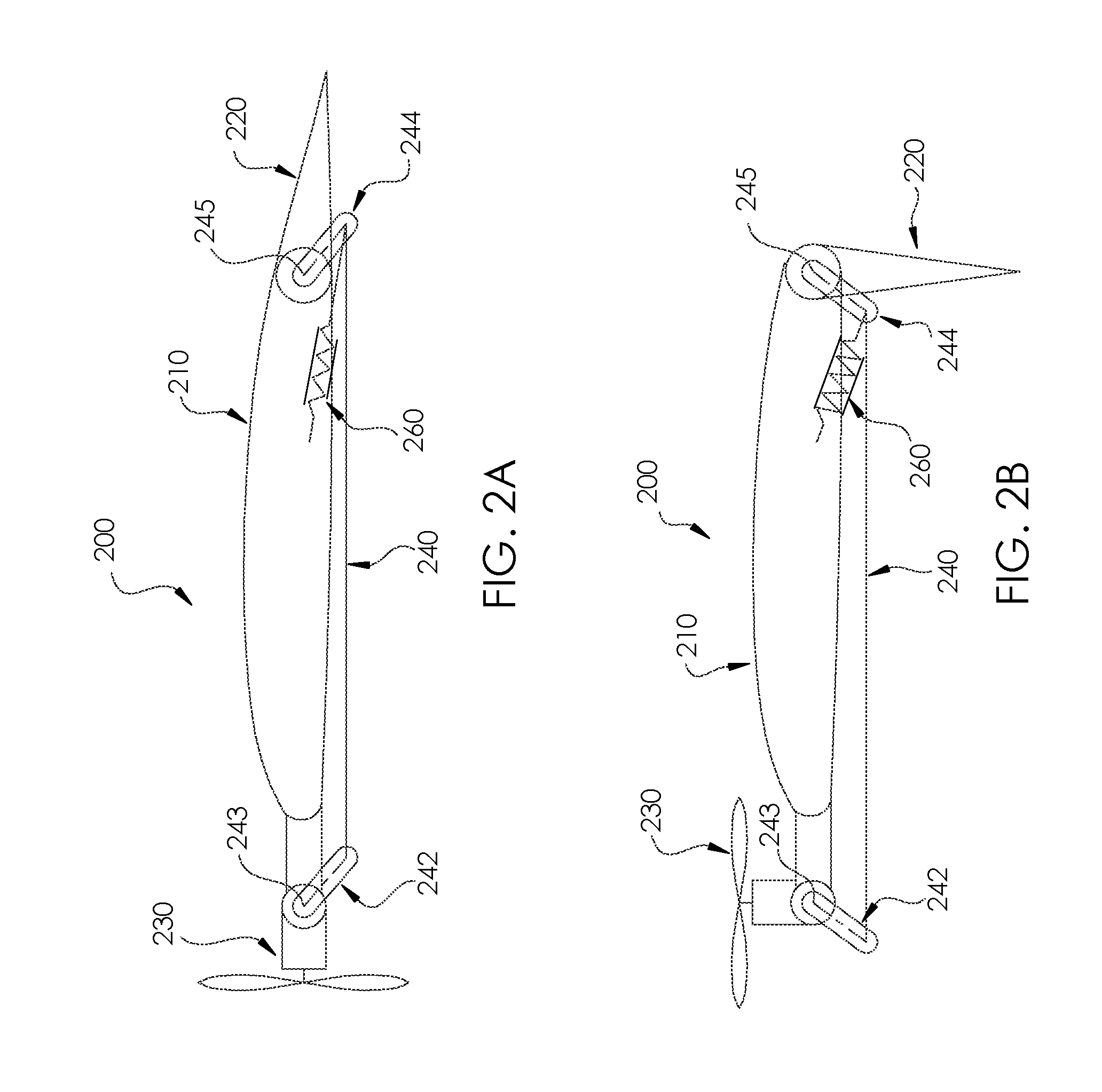
The present invention describes systems and methods for thrust vectoring devices for aircraft vehicles. The invention is particularly useful for tilt-wing or tilt-propulsor aircraft. The thrust actuating device includes a control surface pivotably attached to a wing and a propulsor configured to rotate between a first position for homing and a second position for forward flight mode. The device can also include a series of aerodynamically actuated propulsors that move along with the wing as it tilts through a range of motion. The invention allows for efficient and effective control of the aircraft's thrust vectoring during various flight modes.

Problems solved by technology

Prior art solutions for thrust vectoring system have not resolved the need for an approach to perform one or more of the above actions without drawbacks, e.g., mechanical / electrical complexity, size and weight constraints, and / or cost-prohibitive.

Method used


Image

  • Aerodynamically Actuated Thrust Vectoring Devices
  • Aerodynamically Actuated Thrust Vectoring Devices
  • Aerodynamically Actuated Thrust Vectoring Devices

Examples


Embodiment Construction

[0020]For purposes of description herein, the terms “upper,”“lower,”“right,”“left,”“rear,”“front,”“vertical,”“horizontal,” and derivatives thereof shall relate to the invention as oriented in the attached drawings. However, it is to be understood that the invention may assume various alternative orientations and step sequences, except where expressly specified to the contrary. It is also to be understood that the specific devices and processes illustrated in the attached drawings, and described in the following specification, are simply exemplary embodiments of the inventive concepts defined in the appended claims. Hence, specific dimensions and other physical characteristics relating to the embodiments disclosed herein are not to be considered as limiting, unless the claims expressly state otherwise.

[0021]In the following description of various examples of the invention, reference is made to the accompanying drawings which show, by way of illustration, various example systems and e...


PUM


Abstract

A vehicle includes a wing and a control surface pivotably coupled to the wing and configured to pivot about a range of motion. A propulsor is coupled to the control surface and configured to rotate between a first position associated with a hover flight mode and a second position associated with a forward flight mode. The propulsor is aerodynamically actuated between the first position and the second position due to aerodynamics about the wing. The propulsor may rotate from an initial flight mode, such as a takeoff mode, to a second flight mode, such as a forward flight mode.

Description

CROSS-REFERENCE TO RELATED PATENT APPLICATION[0001]This patent application claims the benefit of and priority to U.S. Provisional Patent Application No. 62 / 137,546, filed on Mar. 24, 2015, the contents of which are hereby incorporated by reference in their entirety.STATEMENT REGARDING FEDERALLY SPONSORED RESEARCH OR DEVELOPMENT[0002]The invention described herein was made in part by employees of the United States Government and may be manufactured and used by and for the Government of the United States for governmental purposes without the payment of any royalties thereon or therefore.BACKGROUND OF THE INVENTION[0003]Thrust vectoring is an essential feature for vehicles capable of transitioning in flight direction and / or transitioning between various types of flight modes, such as from a takeoff mode to a forward flight mode. In particular, propulsors (e.g., propellers, rotors, fans, ducted fans, or other thrust generating devices that accelerate air) may be designed to rotate or ti...

Claims


Application Information

Patent Timeline
IPC IPC(8): B64C29/00B64C15/12B64C9/04
CPCB64C29/0033B64C15/12B64C9/04Y02T50/30Y02T50/40
Inventor ROTHHAAR, PAUL M.FREDERICKS, WILLIAM J.NORTH, DAVID D.
Owner NASA
Learn More