Telescoping joint

a technology of telescopic joints and joints, applied in the direction of rod connections, lighting support devices, lighting and heating apparatuses, etc., can solve problems such as the head portion drooping due to a lack of telescopic joints

Inactive Publication Date: 2016-10-06
KONCEPT TECH
View PDF9 Cites 5 Cited by
  • Summary
  • Abstract
  • Description
  • Claims
  • Application Information

AI Technical Summary

Benefits of technology

[0009]Accordingly, particular embodiments provide frictional forces for preventing drooping and collapsing of the adjustable structure (with respect to the inner tube member and the outer tube member) while allowing the inner tube member and the outer tube member to be adjusted (e.g., moved in the linear, telescoping and / or rotational direction) smoothly. In embodiments in which the first frictional element and the second frictional element may be adjusted independent of one another, the appropriate amount of frictional force (e.g., the first frictional force or the second frictional force) may be provided in either the telescoping or rotational direction to allow manual adjustment of the relative linear or rotational position of the tube members, and to maintain the tube members in the adjusted position. In this manner, the first and second frictional forces may be independently selected so as to allow a user to easy make manual adjustments to the relative positions of the tube members in the linear and / or rotational directions, where such adjustments are frictionally maintained, without imparting frictional forces in the other of the linear and / or rotational directions so great as to interfere with or inhibit manual adjustment of the tube members in that other direction.

Problems solved by technology

However, the head portion may have a mass (or weight) that can cause the head portion to droop due to gravity, if not sufficiently supported.

Method used


Image

  • Telescoping joint
  • Telescoping joint
  • Telescoping joint

Examples


Embodiment Construction

[0026]In the following description of preferred embodiments, reference is made to the accompanying drawings which form a part hereof and in which are shown by way of illustration specific embodiments in which the invention may be practiced. It is to be understood that other embodiments may be utilized and structural changes may be made without departing from the scope of the preferred embodiments of the present disclosure.

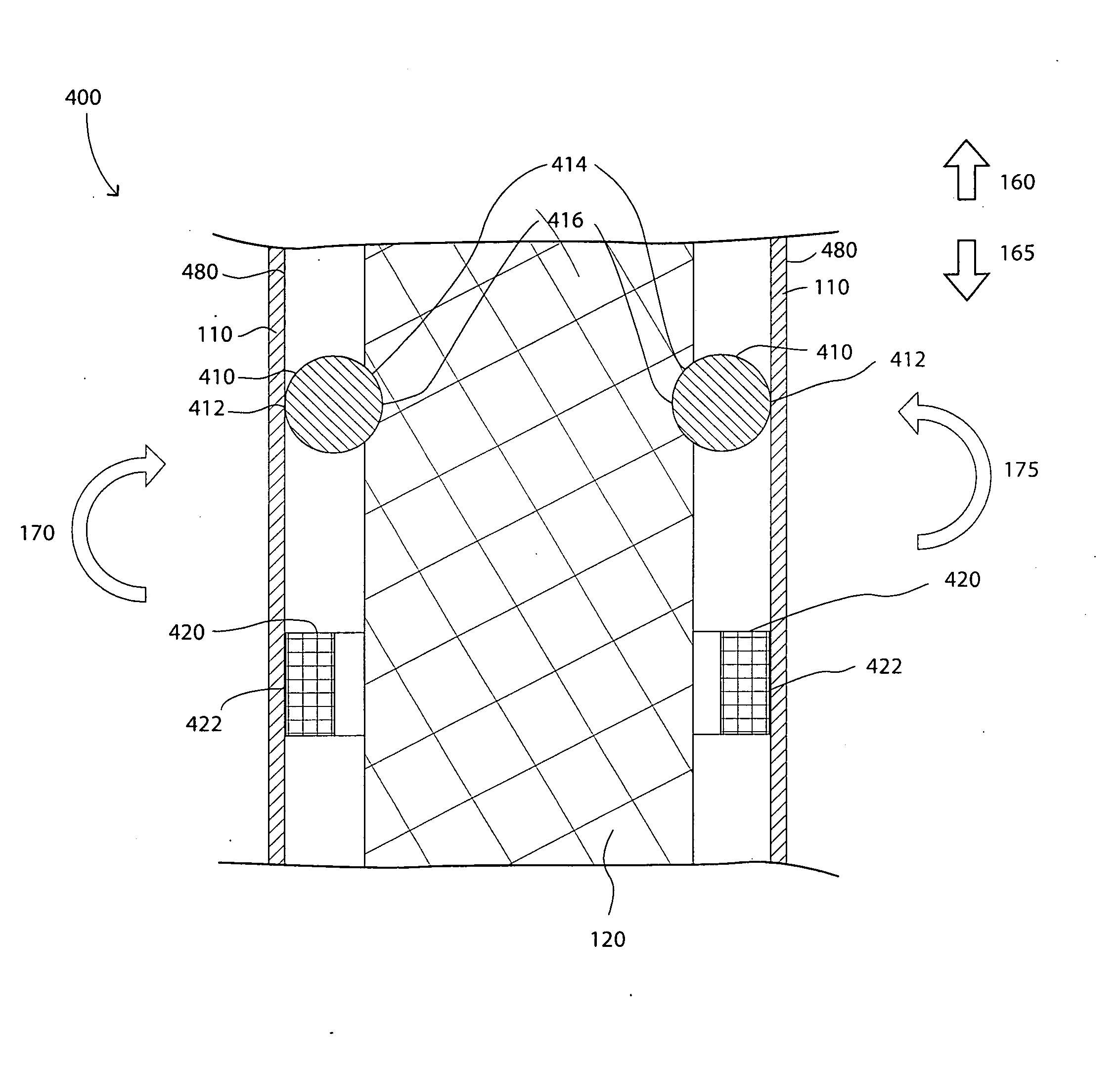
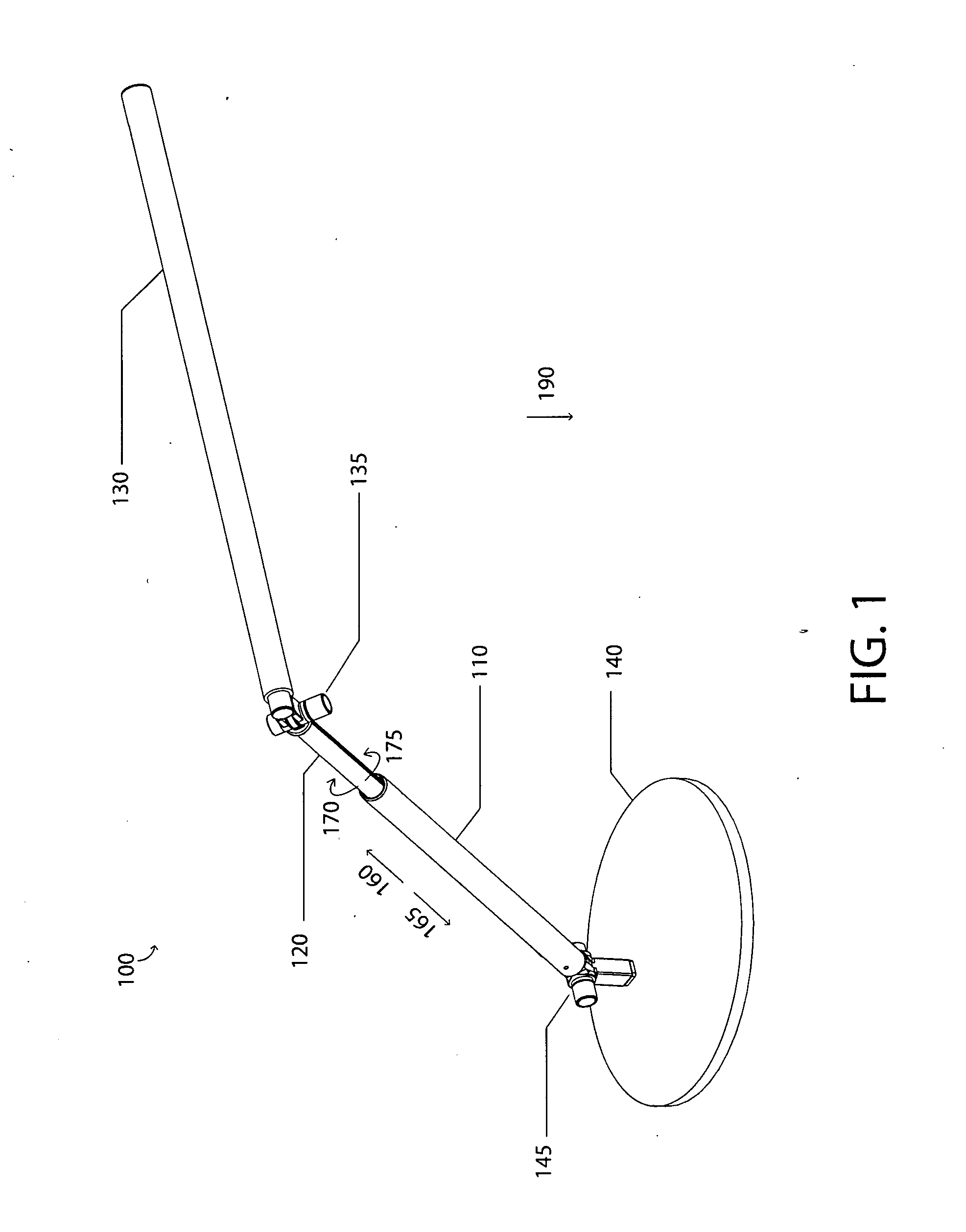
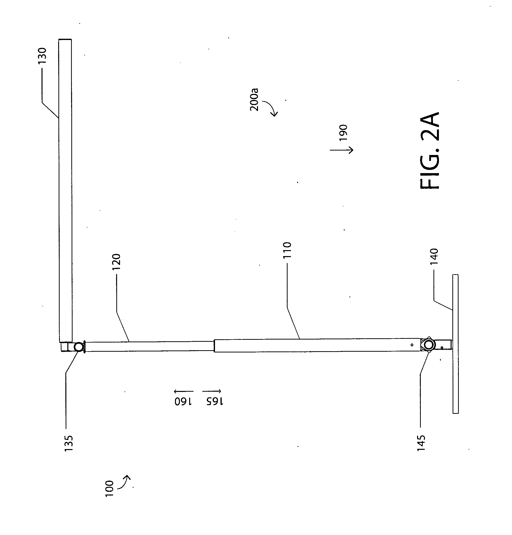
[0027]Referring generally to the features, embodiments described herein relate to an adjustable structure (such as, but not limited to, a flexible adjustable desk lamp) having a telescopic arm structure. The telescopic arm structure may include at least two members configured for telescoping and rotational movements with respect to each other. Examples of the two members include, but are not limited to, an inner tube member and an outer tube member arranged coaxially, with the inner tube member at least partially within the outer tube member.

[0028]The first compone...


PUM


Abstract

An adjustable structure is described herein according to various embodiments, including an inner tube member and an outer tube member. The inner tube member and the outer tube member are configured to move in at least one of a telescoping direction or a rotation direction with respect to one another. The adjustable structure further includes a first frictional element between the inner tube member and the outer tube member. The first frictional element provides friction in the telescoping direction. Furthermore, the adjustable structure includes a second frictional element between the inner tube member and the outer tube member. The second frictional element provides friction in the rotational direction.

Description

BACKGROUND[0001]1. Field[0002]The present disclosure relate to structures for providing frictional forces between two members configured for movement with respect to each other, and in particular embodiments, to at least one bushing structure or joint configured to exert frictional forces between the two members configured to engage in telescoping and / or rotational movements with respect to each other. Particular embodiments relate to supporting structures having one or more of such bushing structures or joints for supporting light-emitting elements or other electronic or operational devices, and lamps or other electronic or operational devices that include such supporting structures.[0003]2. Background[0004]Lamp configurations (e.g., a desk lamp, floor lamp, wall light, slim adjustable LED lamp, or the like) can be configured with telescoping tube members that support light-emitting elements, where the telescoping tube members allow for adjustable movement (e.g., vertical up or dow...

Claims


Application Information

Patent Timeline
Patent Type & Authority Applications(United States)
IPC IPC(8): F16B7/14
CPCF16B7/14F21S6/002F21S6/005F21V21/22
Inventor NG, HON KIT PETERNG, KENNETH YAT CHUNGNG, EDMUND YAT KWONG
Owner KONCEPT TECH
Why Eureka
Try Eureka