This helps you quickly interpret patents by identifying the three key elements:
Problems solved by technology
Method used
Benefits of technology
Benefits of technology
The invention improves the tire's ability to corner and reduces the side force generated during travel. It also enhances steering stability.
Problems solved by technology
In a pneumatic tire of the related art that is filled with pressurized air and used, the occurrence of a blowout is a structurally unavoidable problem.
Method used
Image
Click on the blue label to locate the original text in one second.
Reading with bidirectional positioning of images and text.
Examples
first embodiment
[0045]Hereinafter, a first embodiment of a non-pneumatic tire according to the present invention will be described with reference to FIGS. 1 to 6.
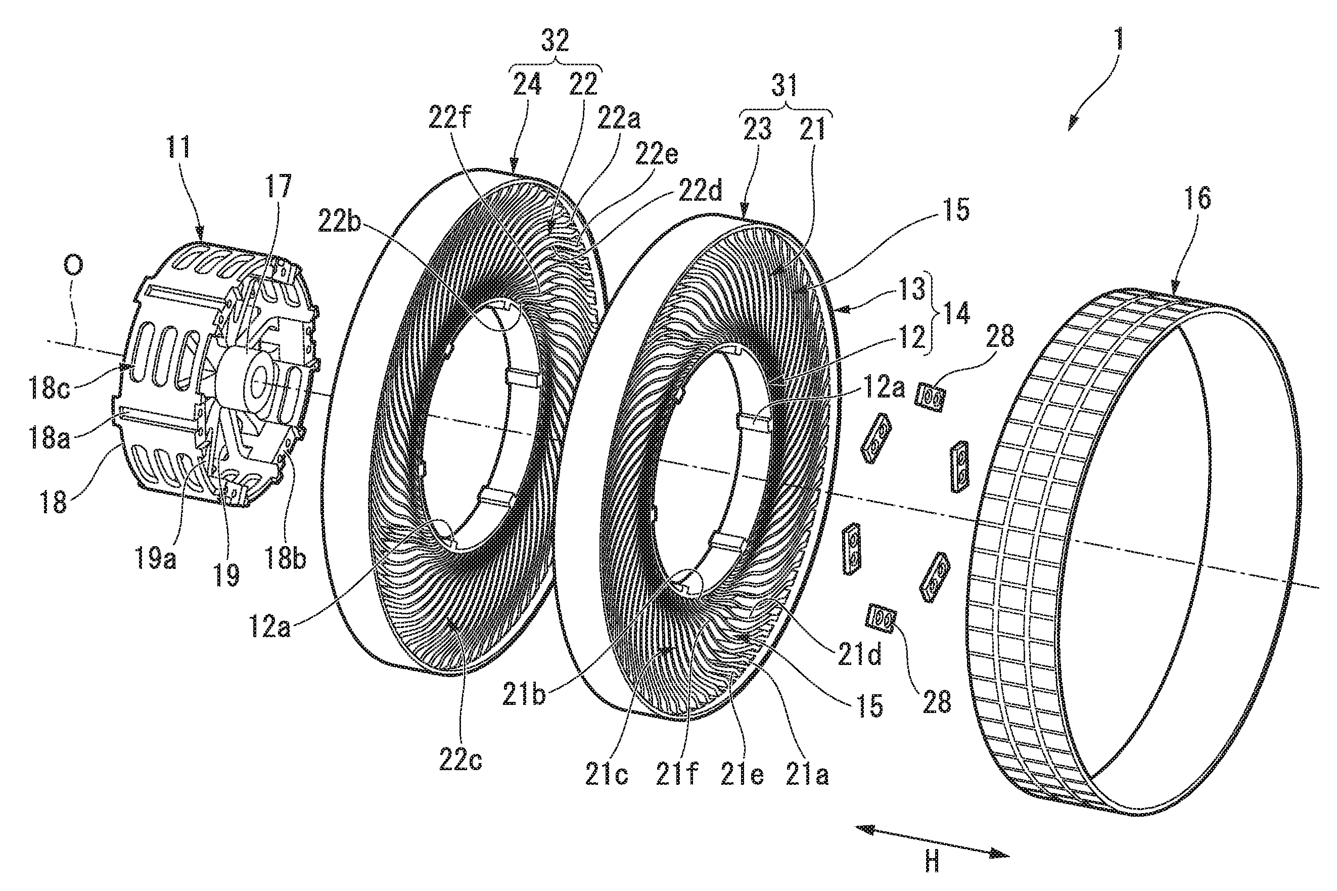
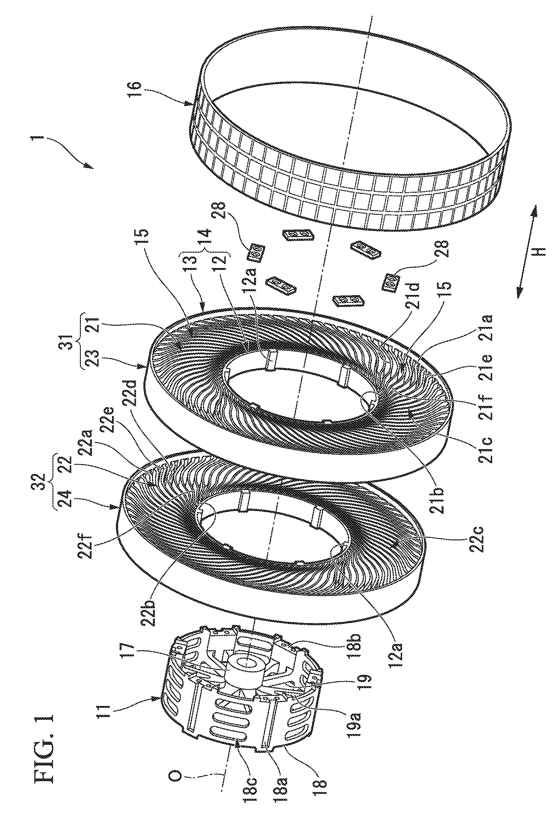
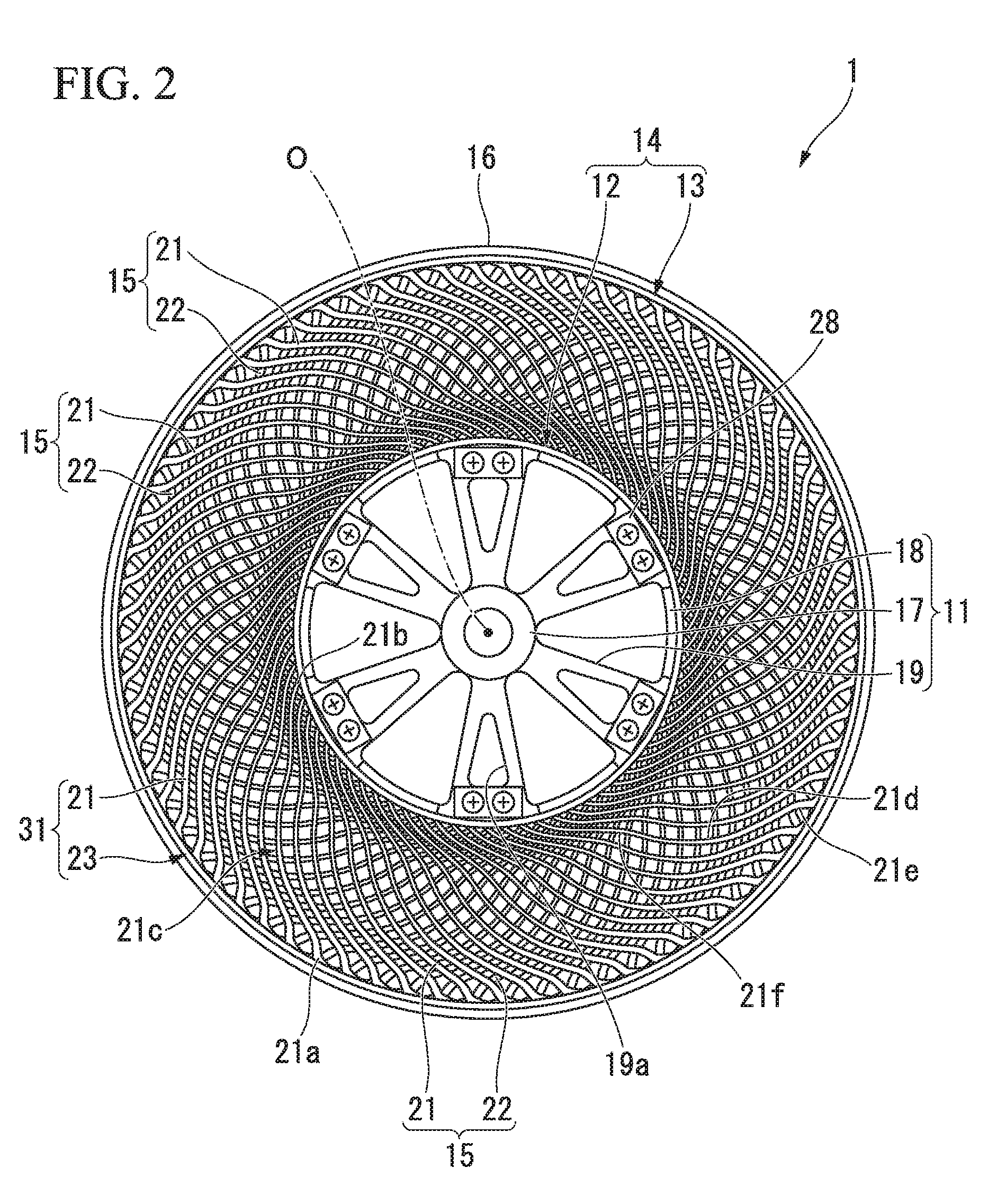
[0046]A non-pneumatic tire 1 includes an attachment body 11 attached to an axle (not shown), a ring member 14 including an inner tubular body 12 fitted onto the attachment body 11 and an outer tubular body 13 configured to surround the inner tubular body 12 from the outside in a tire radial direction, a plurality of connecting members 15 disposed between the inner tubular body 12 and the outer tubular body 13 in a tire circumferential direction and connecting the tubular bodies 12 and 13 to each other while allowing relative elastic displacement therebetween, and a tread member 16 disposed at an outer circumferential surface side of the outer tubular body 13 throughout the circumference.
[0047]Here, the attachment body 11, the inner tubular body 12, the outer tubular body 13 and the tread member 16 are disposed coaxially with a common axis....
second embodiment
[0100]Next, a non-pneumatic tire according to a second embodiment of the present invention will be described with reference to FIG. 7.
[0101]Further, in the second embodiment, the same portions as the components of the first embodiment will be designated by the same reference numerals, a description thereof will be omitted, and only differences will be described.
[0102]In a non-pneumatic tire 2 of the embodiment, as shown in FIG. 7, an outer circumferential surface of the tread member 16 forms a convex shape protruding outward in the tire radial direction when seen in a cross-sectional view in the tire width direction H, and an outer diameter of the tread member 16 is gradually reduced as it recedes from a maximum outer diameter portion 16a thereof in the tire width direction H. Further, an outer diameter of the tread member 16 is a distance in the tire radial direction between the outer circumferential surface of the tread member 16 and the axis O. The maximum outer diameter portion ...
third embodiment
[0105]Next, a non-pneumatic tire according to a third embodiment of the present invention will be described with reference to FIG. 8.
[0106]Further, in the third embodiment, the same portions as the components of the first embodiment will be designated by the same reference numerals, a description thereof will be omitted, and only differences will be described.
[0107]In a non-pneumatic tire 3 of the embodiment, each of both types of the elastic connecting plates 21 and 22 extends outward in the tire width direction H from the attachment body 11 toward the outer tubular body 13. Edges outside in the tire width direction H of each of both types of the elastic connecting plates 21 and 22 are formed in linear shapes inclined with respect to the reference line S when seen in the front view. A member width of the connecting member 15 is gradually increased from the second end portion of the connecting member 15 connected to the attachment body 11 toward the first end portion thereof connect...
PUM
Abstract
In a non-pneumatic tire, central portions in an extension direction of first elastic connecting plates (21) and central portions in an extension direction of second elastic connecting plates (22) are spaced from each other in a tire width direction (H) by a distance of 0.25 to 0.9 times an outer tube width (W1) serving as a size in the tire width direction (H) of an outer tubular body (13), edges of a first side in the tire width direction (H) of first end portions (21a) of the first elastic connecting plates (21) are disposed at the same positions in the tire width direction (H) as edges of the first side in the tire width direction (H) of the outer tubular body (13) or disposed inside in the tire width direction (H) of the edge of the first side in the tire width direction (H) of the outer tubular body (13) within a distance of 0.1 times the outer tube width (W1) or less, and edges of a second side in the tire width direction (H) of first end portions (22a) of the second elastic connecting plates (22) are disposed at the same positions in the tire width direction (H) as an edge of the second side in the tire width direction (H) of the outer tubular body (13) or disposed inside in the tire width direction (H) of the edge of the second side in the tire width direction (H) of the outer tubular body (13) within a distance of 0.1 times the outer tube width (W1) or less.
Description
TECHNICAL FIELD[0001]The present invention relates to a non-pneumatic tire that can be used without being filled with pressurized air.[0002]Priority is claimed on Japanese Patent Application Nos. 2013-237104 and 2013-237105, filed Nov. 15, 2013, the contents of which are incorporated herein by reference.BACKGROUND ART[0003]In a pneumatic tire of the related art that is filled with pressurized air and used, the occurrence of a blowout is a structurally unavoidable problem.[0004]In order to solve this problem, in recent years, for example, as disclosed in the following Patent Document 1, a non-pneumatic tire including an attachment body attached to an axle, an outer tubular body configured to surround the attachment body from the outside in a tire radial direction, and a connecting member configured to connect the attachment body and the outer tubular body while allowing a displacement therebetween has been proposed.DOCUMENT OF RELATED ARTPatent Document[Patent Document 1][0005]Japane...
Claims
Application Information
Patent Timeline
Application Date:The date an application was filed.
Publication Date:The date a patent or application was officially published.
First Publication Date:The earliest publication date of a patent with the same application number.
Issue Date:Publication date of the patent grant document.
PCT Entry Date:The Entry date of PCT National Phase.
Estimated Expiry Date:The statutory expiry date of a patent right according to the Patent Law, and it is the longest term of protection that the patent right can achieve without the termination of the patent right due to other reasons(Term extension factor has been taken into account ).
Invalid Date:Actual expiry date is based on effective date or publication date of legal transaction data of invalid patent.

