
Pneumatic tire

Inactive Publication Date: 2006-01-05
BRIDGESTONE CORP
View PDF4 Cites 10 Cited by
  • Summary
  • Abstract
  • Description
  • Claims
  • Application Information

AI Technical Summary

Benefits of technology

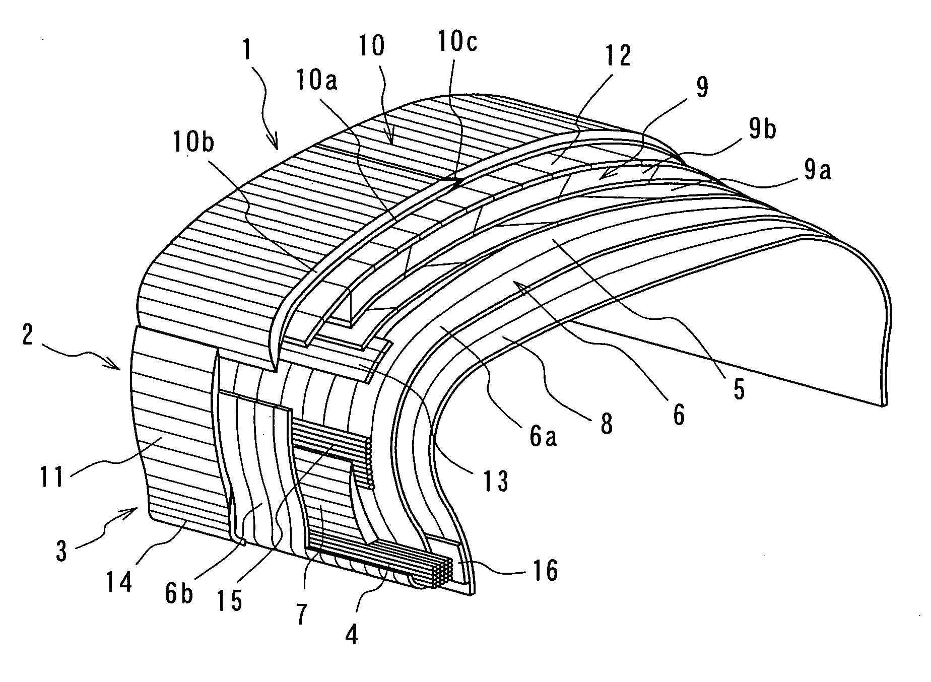
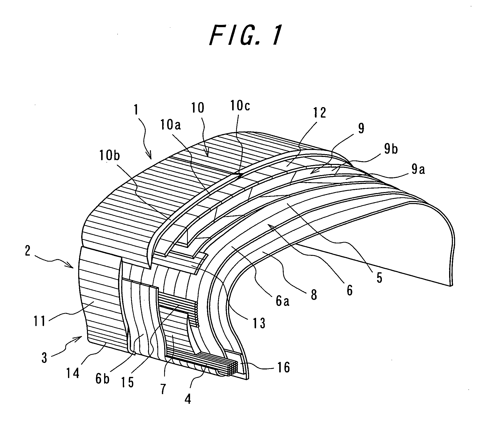
[0006] According to the invention, the plurality of the joints through the overlap or butt joining existing in one or more layers of the innerliner, carcass ply and belt layer are equally and dispersedly positioned at the constant intervals in the peripheral direction, and these joints formed in each layer are sufficiently balanced statically and dynamically between the mutual joints, so that the joints in each layer can effectively contribute to the realization of excellent uniformity and high balance in the tire without considering the relative position of the joint between the one layer and the other layer and the like. This is particularly effective when the joints are arranged in all of the innerliner, the carcass ply and the belt layer at approximately constant intervals in the peripheral direction.
[0021] In this case, the joint portion extending in the meridional direction of the tire can be eliminated as far as possible likewise the aforementioned joints in each of the tread rubber, the bead filler rubber and the side rubber to more effectively improve the uniformity and the balance of the tire.

Problems solved by technology

Further, there is no guarantee that such an overlap joint portion is equally dispersed in the peripheral direction of the building drum between these materials, so that even if a counter-measure for suppressing the increase of the thickness in the overlap joint portion is taken in each of the materials, it is unavoidable to necessarily lower the uniformity and the balance of a product tire produced by vulcanizing the green tire.

Method used


Image

  • Pneumatic tire
  • Pneumatic tire
  • Pneumatic tire

Examples


examples

[0051] There are provided example tires having a structure according to the invention and a tire size of 235 / 45 ZR17 in which joints positioned at approximately constant intervals in the peripheral direction are arranged in at least one of the innerliner, the carcass ply and the belt layer and joints positioned at intervals in a direction along an outer profile at the meridional section of the tire and continuously extending substantially in the peripheral direction are formed in each of the tread rubber, the bead filler rubber and the side rubber, and a radial force variation (hereinafter referred to as RFV) is measured as an indication of the uniformity and a static balance is measured as an indication of the balance to obtain results shown in FIG. 5.

[0052] Moreover, the static balance is determined by setting the tire onto a balancer and attaching a weight to a side portion corresponding to a light point position of the tire so as to render an unbalance quantity into zero to mea...


PUM


Abstract

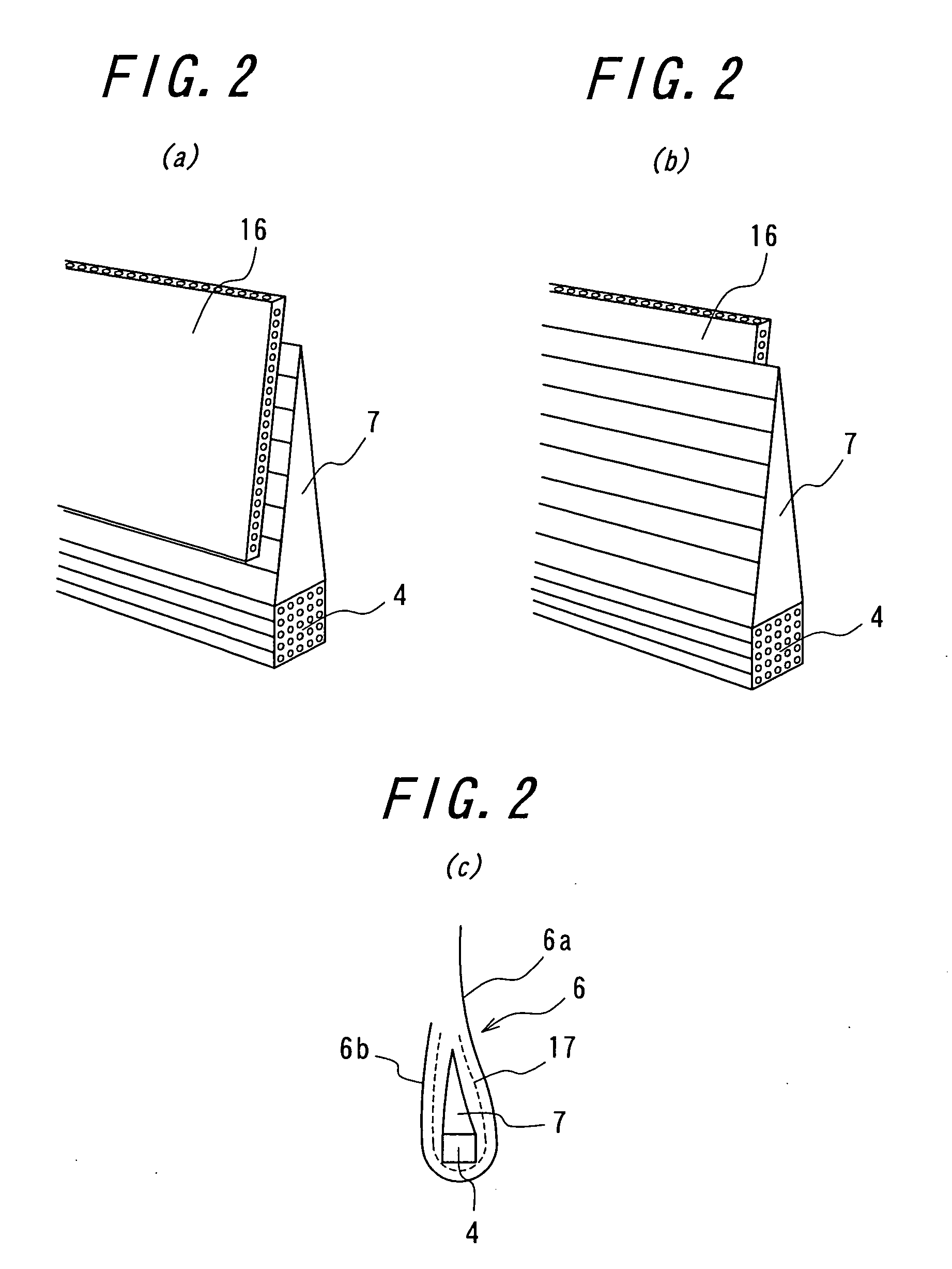
There is provided a pneumatic tire having considerably improved uniformity and balance, which comprises a radial carcass comprised of one carcass ply, a bead filler rubber arranged at an outer peripheral side of a bead core, an innerliner arranged at an inner face side of the carcass, a belt comprised of two belt layers, a tread rubber forming a treading face, and a side rubber arranged at an outer face side of a side portion of the carcass to form a sidewall of the tire, in which joints positioned at approximately equal intervals in the peripheral direction are arranged in each of the innerliner, the carcass ply and the belt layer, and joints positioned at intervals in a direction along an outer profile at a meridional section of the tire and extending substantially in the peripheral direction are arranged in each of the tread rubber, the bead filler rubber and the side rubber.

Description

TECHNICAL FIELD [0001] This invention relates to a pneumatic tire built on a building drum having a basic form of substantially a cylinder, and particularly proposes a technique of largely improving a uniformity and a balance of the tire. BACKGROUND ART [0002] In general, the conventional building of a green tire using a building drum is carried out by forming a green case comprised of an innerliner, a carcass, bead cores, side rubbers and the like on a building drum, transferring the green case onto another building drum, conducting a tire building so as to expand and deform a central portion of the green case in a radial direction, and affixing a previously formed belt-tread band onto an outer peripheral thereof. [0003] When the green tire is built under the action of the building drums, if an innerliner material, carcass ply material, belt material, tread rubber material and the like each previously cut into given length and width are affixed on the building drum over a full peri...

Claims


Application Information

Patent Timeline
IPC IPC(8): B60C17/00B60C9/02B60C9/18B60C9/22B60C11/00B60C13/00B60C15/06B60C5/14B60C19/08B60C1/00B60C9/04B60C9/20
CPCB60C13/00B60C15/06B60C17/0018B60C17/0027Y10T152/10828Y10T152/10864Y10T152/10855Y10T152/10765Y10T152/10495
Inventor HIRAI, NOBUYUKI
Owner BRIDGESTONE CORP
Learn More