Non-pneumatic tire
a technology of non-pneumatic tires and tires, which is applied in the direction of tyre parts, transportation and packaging, and other domestic objects, can solve the problems of structural unavoidable problems such as blowouts, and achieve the effects of improving steering stability, improving cornering performance of tires, and limited lateral force generated during travel
- Summary
- Abstract
- Description
- Claims
- Application Information
AI Technical Summary
Benefits of technology
Problems solved by technology
Method used
Image
Examples
first embodiment
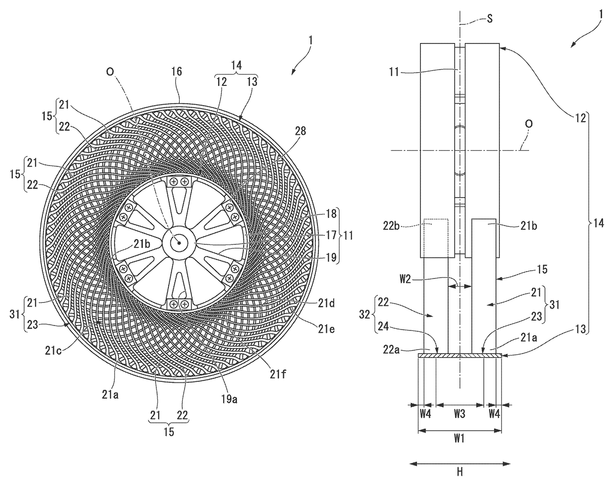
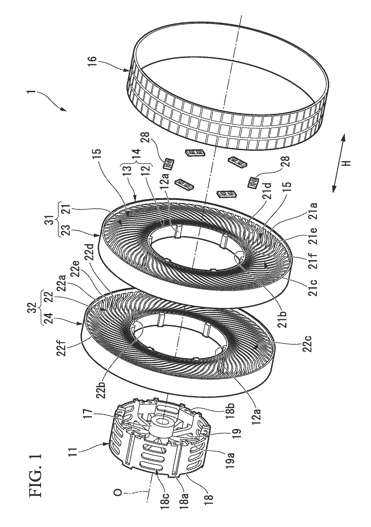
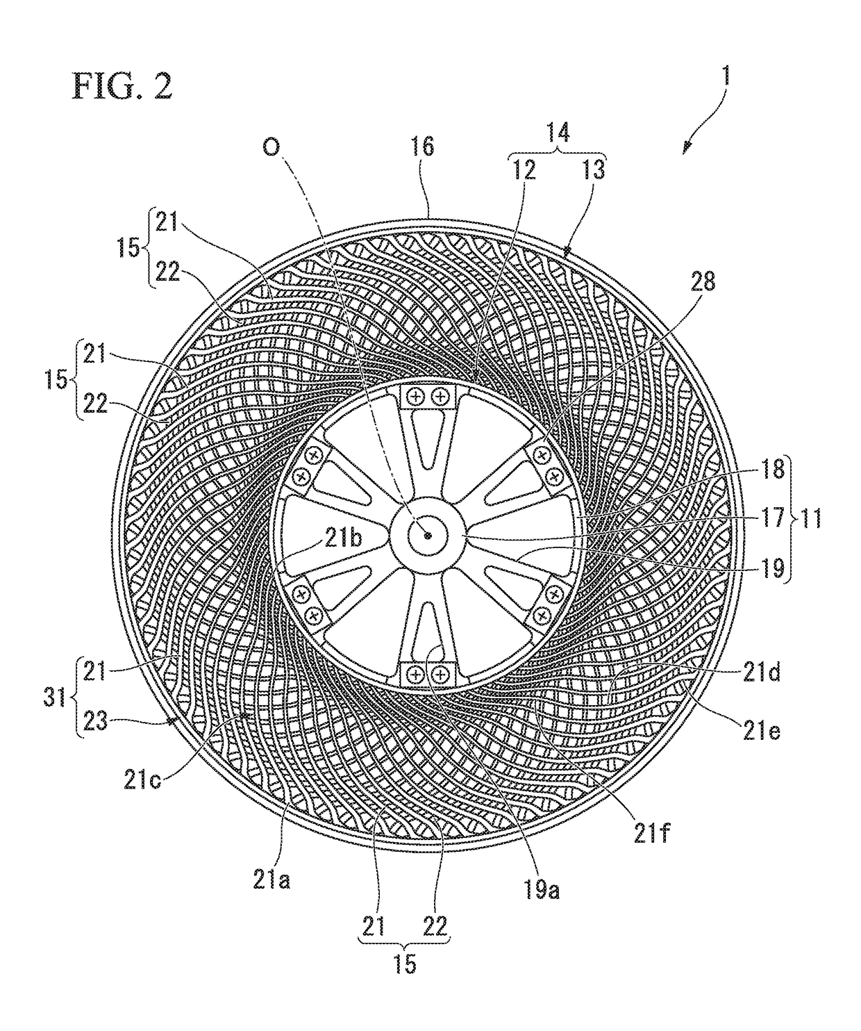
[0045]Hereinafter, a first embodiment of a non-pneumatic tire according to the present invention will be described with reference to FIGS. 1 to 6.
[0046]A non-pneumatic tire 1 includes an attachment body 11 attached to an axle (not shown), a ring member 14 including an inner tubular body 12 fitted onto the attachment body 11 and an outer tubular body 13 configured to surround the inner tubular body 12 from the outside in a tire radial direction, a plurality of connecting members 15 disposed between the inner tubular body 12 and the outer tubular body 13 in a tire circumferential direction and connecting the tubular bodies 12 and 13 to each other while allowing relative elastic displacement therebetween, and a tread member 16 disposed at an outer circumferential surface side of the outer tubular body 13 throughout the circumference.
[0047]Here, the attachment body 11, the inner tubular body 12, the outer tubular body 13 and the tread member 16 are disposed coaxially with a common axis....
second embodiment
[0100]Next, a non-pneumatic tire according to a second embodiment of the present invention will be described with reference to FIG. 7.
[0101]Further, in the second embodiment, the same portions as the components of the first embodiment will be designated by the same reference numerals, a description thereof will be omitted, and only differences will be described.
[0102]In a non-pneumatic tire 2 of the embodiment, as shown in FIG. 7, an outer circumferential surface of the tread member 16 forms a convex shape protruding outward in the tire radial direction when seen in a cross-sectional view in the tire width direction H, and an outer diameter of the tread member 16 is gradually reduced as it recedes from a maximum outer diameter portion 16a thereof in the tire width direction H. Further, an outer diameter of the tread member 16 is a distance in the tire radial direction between the outer circumferential surface of the tread member 16 and the axis O. The maximum outer diameter portion ...
third embodiment
[0105]Next, a non-pneumatic tire according to a third embodiment of the present invention will be described with reference to FIG. 8.
[0106]Further, in the third embodiment, the same portions as the components of the first embodiment will be designated by the same reference numerals, a description thereof will be omitted, and only differences will be described.
[0107]In a non-pneumatic tire 3 of the embodiment, each of both types of the elastic connecting plates 21 and 22 extends outward in the tire width direction H from the attachment body 11 toward the outer tubular body 13. Edges outside in the tire width direction H of each of both types of the elastic connecting plates 21 and 22 are formed in linear shapes inclined with respect to the reference line S when seen in the front view. A member width of the connecting member 15 is gradually increased from the second end portion of the connecting member 15 connected to the attachment body 11 toward the first end portion thereof connect...
PUM
| Property | Measurement | Unit |
|---|---|---|
| weight | aaaaa | aaaaa |
| weight | aaaaa | aaaaa |
| displacement | aaaaa | aaaaa |
Abstract
Description
Claims
Application Information
 - R&D
- Intellectual Property
- Life Sciences
- Materials
- Tech Scout
- Unparalleled Data Quality
- Higher Quality Content
- 60% Fewer Hallucinations
Browse by: Latest US Patents, China's latest patents, Technical Efficacy Thesaurus, Application Domain, Technology Topic, Popular Technical Reports.
© 2025 PatSnap. All rights reserved.Legal|Privacy policy|Modern Slavery Act Transparency Statement|Sitemap|About US| Contact US: help@patsnap.com


