Pneumatic Tire

a technology of pneumatic tires and tyres, which is applied in the field of pneumatic tires, can solve problems such as the improvement of braking performance, and achieve the effects of improving the wet performance of tires, increasing the contact patch pressure, and improving the braking performance when traveling on wet surfaces

Active Publication Date: 2015-11-19
THE YOKOHAMA RUBBER CO LTD
View PDF26 Cites 4 Cited by
  • Summary
  • Abstract
  • Description
  • Claims
  • Application Information

AI Technical Summary

Benefits of technology

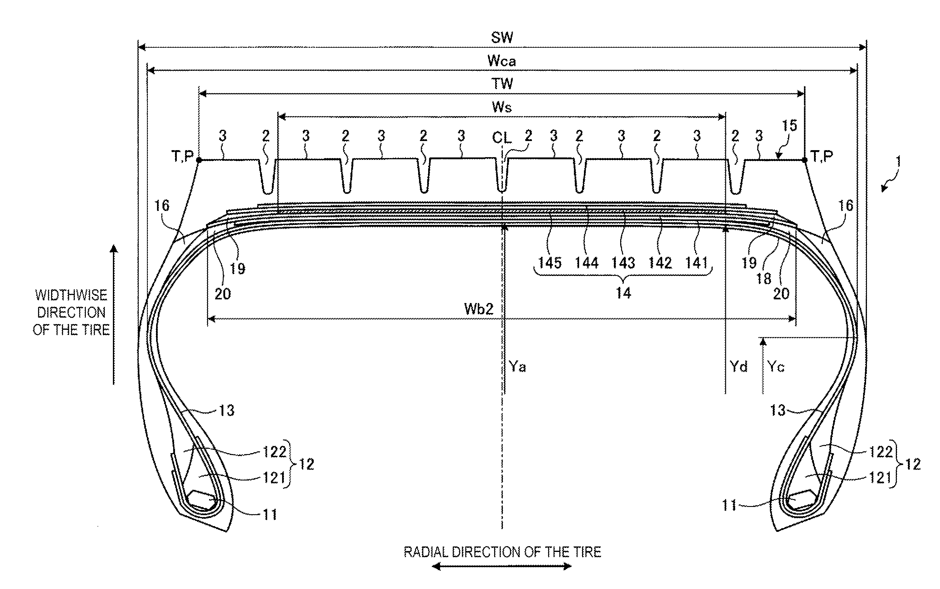
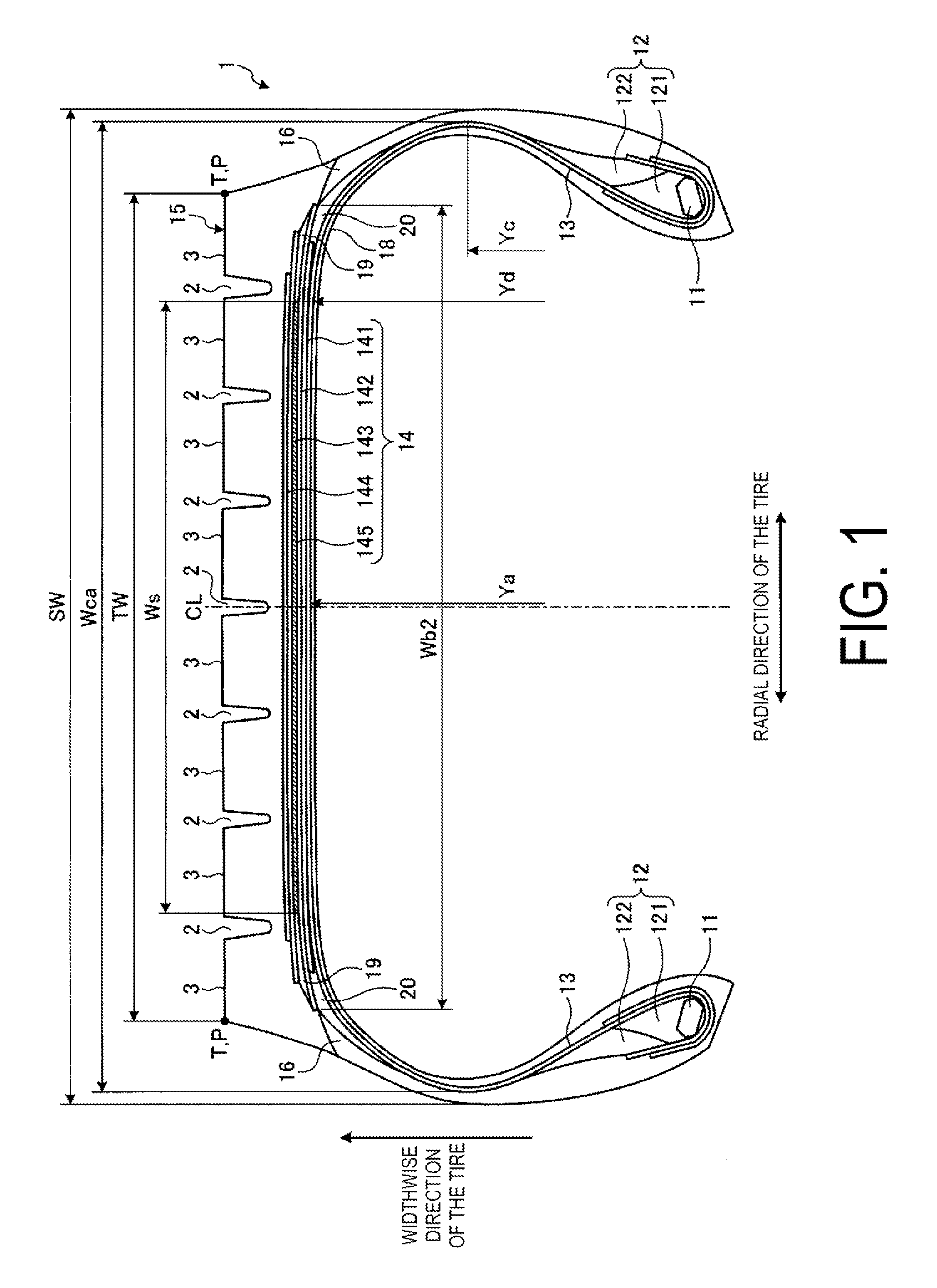
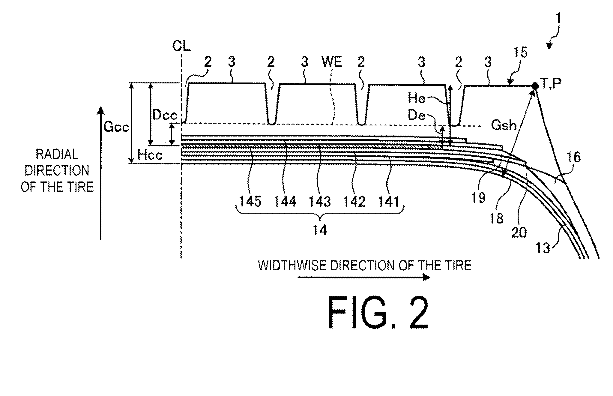
[0007]In the pneumatic tire according to the present technology, (1) the distances Dcc, De of the circumferential reinforcing layer 145 with respect to the end wear surface WE are optimized so as to increase the contact patch pressure at the shoulder land portions when the tire is in contact with the ground. Thereby, braking performance when traveling on wet surfaces is improved, so as to advantageously improve the wet performance of the tire. Additionally, (2) the ratio Wg / Wca of the ground contact width Wg to the cross-sectional width Wca of the carcass layer 13 is optimized, so as advantageously further improve the tire wet performance.
[0008]Additionally, in a pneumatic tire according to the present technology, (1) the distances Dcc, De of the circumferential reinforcing layer 145 with respect to the end wear surface WE are optimized so as to increase the contact patch pressure at the shoulder land portions when the tire is in contact with the ground. Thereby, braking performance when traveling on wet surfaces is improved, so as to advantageously improving the wet performance of the tire. Additionally, (2) the ratio Wg / SW of the ground contact width Wg to the total tire width SW is optimized, so as to advantageously further improve the tire wet performance.

Problems solved by technology

One problem to be addressed in pneumatic tires is the improvement of braking performance when traveling on wet road surfaces.

Method used


Image

  • Pneumatic Tire
  • Pneumatic Tire
  • Pneumatic Tire

Examples


examples

[0135]FIGS. 7A to 10B are tables showing results of performance testing of pneumatic tires according to embodiments of the present technology.

[0136]Performance tests were executed by evaluating the wet performance of a plurality of different pneumatic tires (see FIGS. 7A to 10B). In this evaluation, pneumatic tires having a tire size of 315 / 60 R22.5 were mounted on a rim having a rim size of 22.5×9.00 and inflated with 900 kPa of air pressure. Additionally, the pneumatic tires were mounted on a 2-D (2 front wheels-rear-wheel drive) vehicle as a test vehicle and a load of 30.89 kN was applied to the pneumatic tires.

[0137]Evaluations pertaining to wet performance involved driving the test vehicle on the wet road surface having the pneumatic tires mounted thereon and measuring the braking distance from an initial speed of 60 km / h. Based on the measurement results, index evaluation is carried out, by using the conventional example as a reference (100). A larger numerical value is better...


PUM

PropertyMeasurementUnit
belt angleaaaaaaaaaa

Abstract

A pneumatic tire is provided with at least three circumferential main grooves extending in the circumferential direction of the tire and a plurality of land portions defined by the circumferential main grooves. Additionally, the belt layer is formed by layering a pair of cross belts having a belt angle, as an absolute value, of no less than 10° and no more than 45° and having a belt angles of mutually opposite signs, and a circumferential reinforcing layer having a belt angle within a range of ±5° with respect to a circumferential direction of the tire. A tire ground contact width (Wg) and a carcass cross-sectional width (Wca) of a carcass layer have a relationship such that 0.64≦Wg / Wca≦0.84.

Description

TECHNICAL FIELD[0001]The present technology relates to a pneumatic tire, and in particular to a pneumatic tire with improved wet performance.BACKGROUND[0002]Recent heavy duty tires mounted on trucks, buses, and the like maintain the shape of the tread portion due to the tires having a low aspect ratio while having a circumferential reinforcing layer disposed in the belt layer. The circumferential reinforcing layer is a belt ply having a belt angle that is substantially 0° with respect to the circumferential direction of the tire, and is disposed so as to be layered on a pair of cross belts. The technologies disclosed in Japanese Patent Nos. 4642760, 4663638 and 4663639, as well as in Japanese Unexamined Patent Application Publication (translation of PCT application) No. 2012-522686, are conventional pneumatic tires that are configured in this manner.[0003]One problem to be addressed in pneumatic tires is the improvement of braking performance when traveling on wet road surfaces.SUMM...

Claims


Application Information

Patent Timeline
Patent Type & Authority Applications(United States)
IPC IPC(8): B60C9/18B60C11/04B60C9/00
CPCB60C9/18B60C11/04B60C9/0007B60C9/2006B60C2011/0033B60C9/185B60C9/28B60C2200/06B60C3/04
Inventor KOBAYASHI, HIRONORI
Owner THE YOKOHAMA RUBBER CO LTD
Why Eureka
Try Eureka