

Pneumatic tire
- Summary
- Abstract
- Description
- Claims
- Application Information
AI Technical Summary
Benefits of technology
Problems solved by technology
Method used
Image

Examples
first embodiment
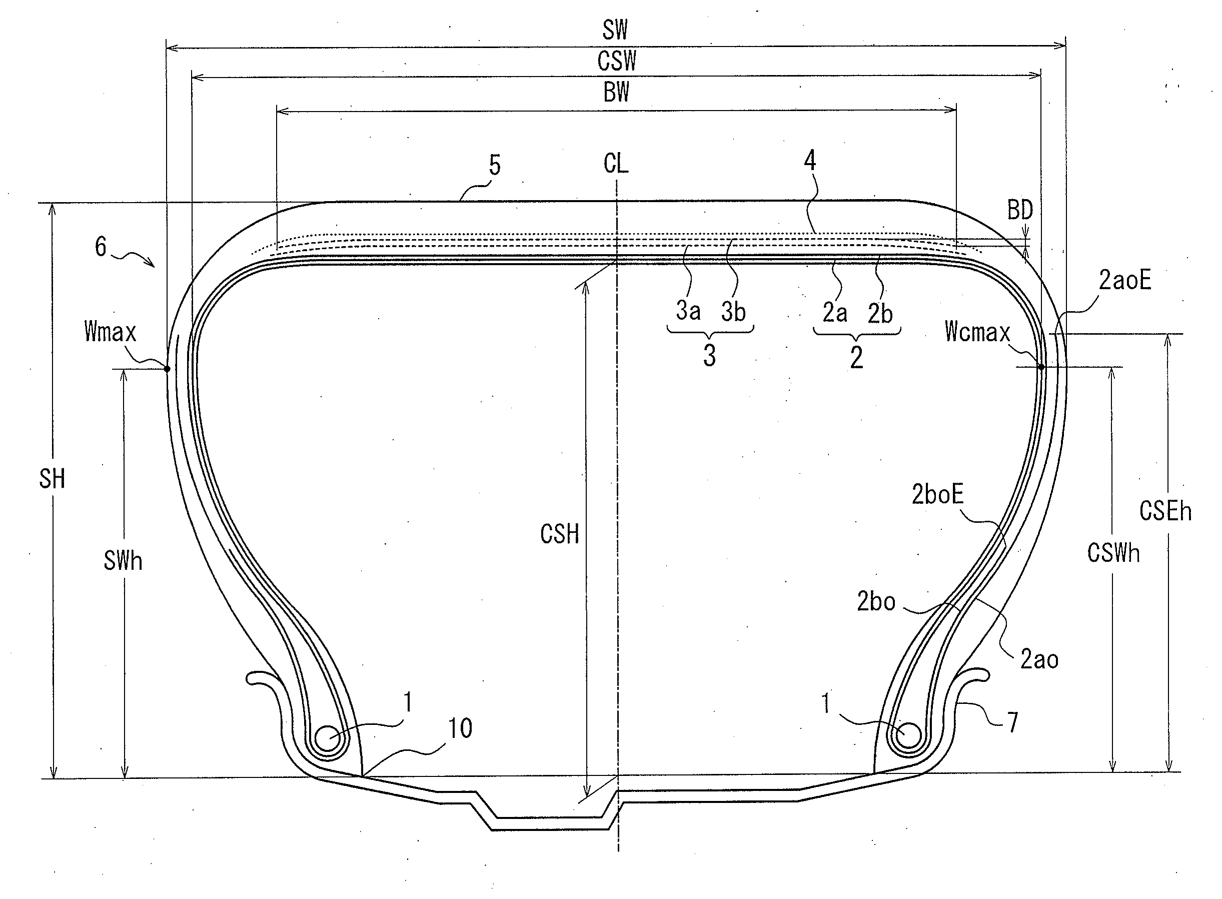
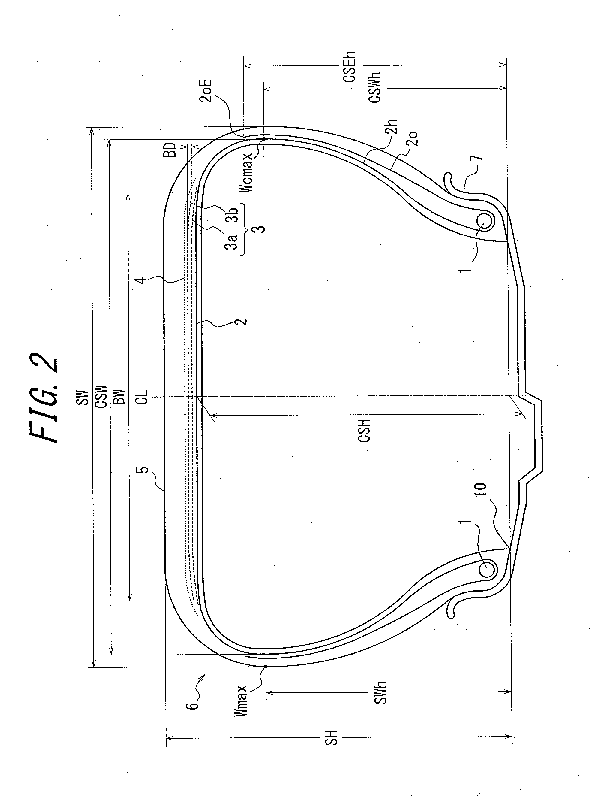
[0031]FIG. 2 shows a widthwise section of a pneumatic tire (hereinafter, referred to as a tire) according to the first embodiment of the present invention. A tire 6 of the present invention comprises a carcass 2 as a framework consisting of at least one carcass ply (one carcass ply in this figure) troidally extending between bead portions embedded with a pair of bead cores 1 and turned around the bead cores 1 from an inner side to an outer side in the tire width direction, a belt comprising at least one inclined belt layer (two inclined belt layers 3a, 3b in this figure) and one circumferential belt layer 4 disposed on a radially outer side of a crown portion of the carcass 2 and a tread 5 disposed on the radially outer side of the belt. The two inclined belt layers 3a, 3b are formed by coating a number of cords extending in a direction inclined with respect to a tire equatorial plane CL with rubber, and the circumferential belt layer 4 is formed by coating a number of cords extendi...
second embodiment
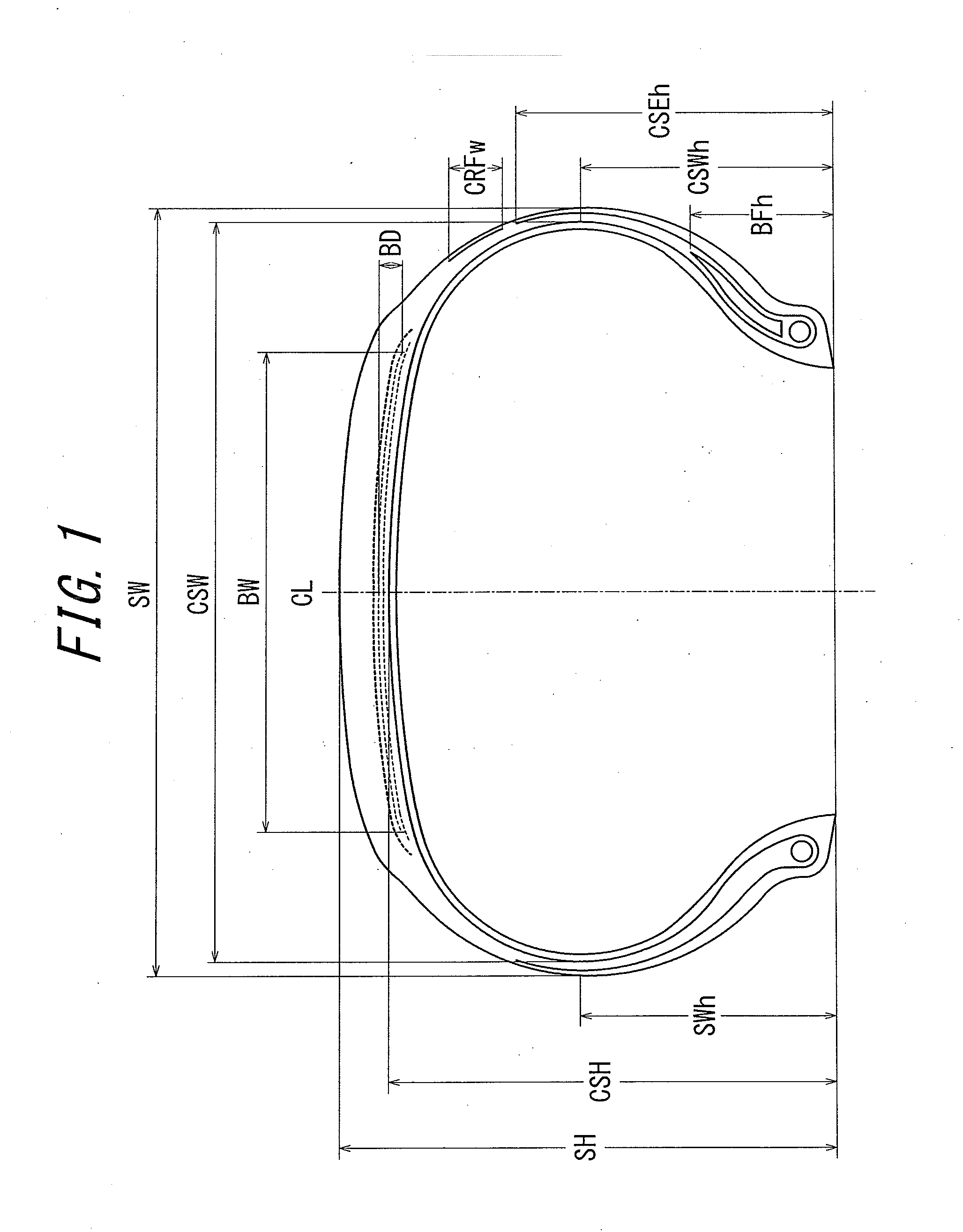
[0060]FIG. 8 shows a widthwise section of a pneumatic tire according to the second embodiment of the present invention. As shown in FIG. 8, a carcass ply reinforcing layer 8 is disposed on a widthwise outer side of the carcass 2 at the maximum width position Wmax of the tire to cover the maximum width position Wmax of the tire. The ratio CRFw / CSH is in a range between 0.2 and 0.6, where CRFw is a width of the carcass ply reinforcing layer 8 and CSH is a distance from a radially outermost side of the carcass 2 to the line drawn in parallel with the tire rotation axis at the bead toe 10 and an reinforcing element embedded in the carcass ply reinforcing layer 8 is inclined at an angle of 30° to 90° with respect to the tire equatorial plane CL.
[0061]Although the carcass ply reinforcing layer 8 is disposed on the widthwise outer side of the turn-up portion 2o of the carcass ply in FIG. 8, the carcass ply reinforcing layer 8 may be disposed between the turn-up portion 2o and the body port...
third embodiment
[0069]FIG. 9 shows a widthwise section of a pneumatic tire according to the third embodiment of the present invention. As shown in FIG. 9, the ratio BFh / CSH is in a range between 0.04 and 0.40, where BFh is the height of a bead filler 9 and CSH is a distance from a radially outermost side of the carcass 2 to the line drawn in parallel with the tire rotation axis at the bead toe 10. The height BFh of the bead filler 9 means a distance from a radially outermost side of the bead filler 9 to the line drawn in parallel with the tire rotation axis at the bead toe 10.
[0070]The turn-up portion 2o of the carcass ply is overlapped with the body portion 2h of the carcass ply at the maximum width position Wmax of the tire on which bending of the side portion is concentrated to reinforce this position and the bead filler 9 is set small so that the bending deformation is applied to the whole side portion under load and therefore, the bending deformation can be prevented from being concentrated on...
PUM
 Abstract
Description
Claims
Application Information