
Vessel and method for delivery of precursor materials

Active Publication Date: 2016-10-20
VERSUM MATERIALS US LLC
View PDF5 Cites 8 Cited by
  • Summary
  • Abstract
  • Description
  • Claims
  • Application Information

AI Technical Summary

Benefits of technology

The patent describes improved ways of using precursors in a vessel for delivering them to a deposition process. The improvements are designed to increase the utilization of the precursors and make the cleaning and refilling of the vessel easier. The patent also mentions a flange that prevents flow communication between the lower volume and the outlet chamber through the first aperture, which helps to further improve the efficiency of the vessel.

Problems solved by technology

One challenge associated with conventional vessels that deliver chemical vapor from a solid precursor by sublimation is a difficulty in obtaining high utilization of precursor.
One cause of this problem is that, in conventional solid source vessels, the distance between the surface of the precursor and the inlet and outlets used to circulate the carrier gas, as well as the volume of the area in which the carrier gas contacts the precursor vapor, increases as the precursor is exhausted.
Although these efforts have resulted in improvements in precursor utilization, the structures needed to implement these improvements can make the vessels more difficult to clean and there is a need for further improvement in the precursor utilization.

Method used


Image

  • Vessel and method for delivery of precursor materials
  • Vessel and method for delivery of precursor materials
  • Vessel and method for delivery of precursor materials

Examples


example

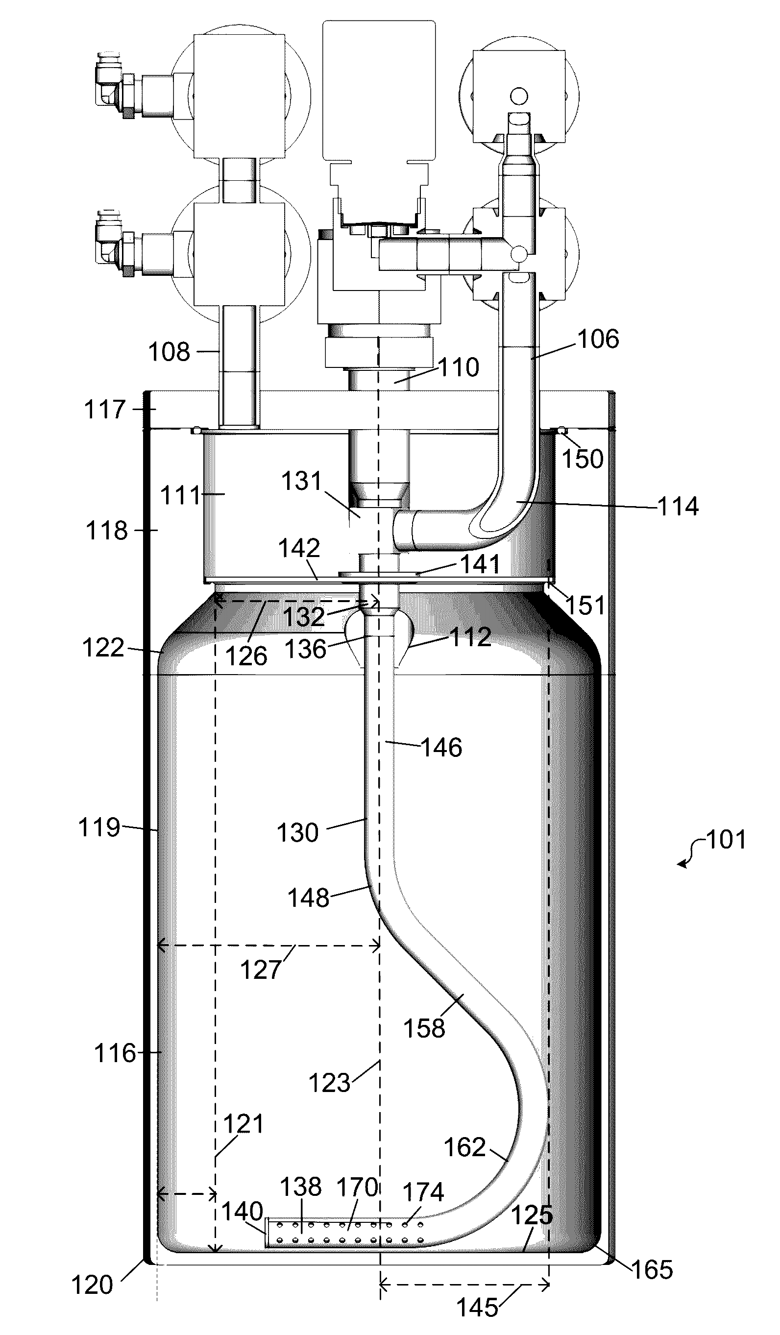
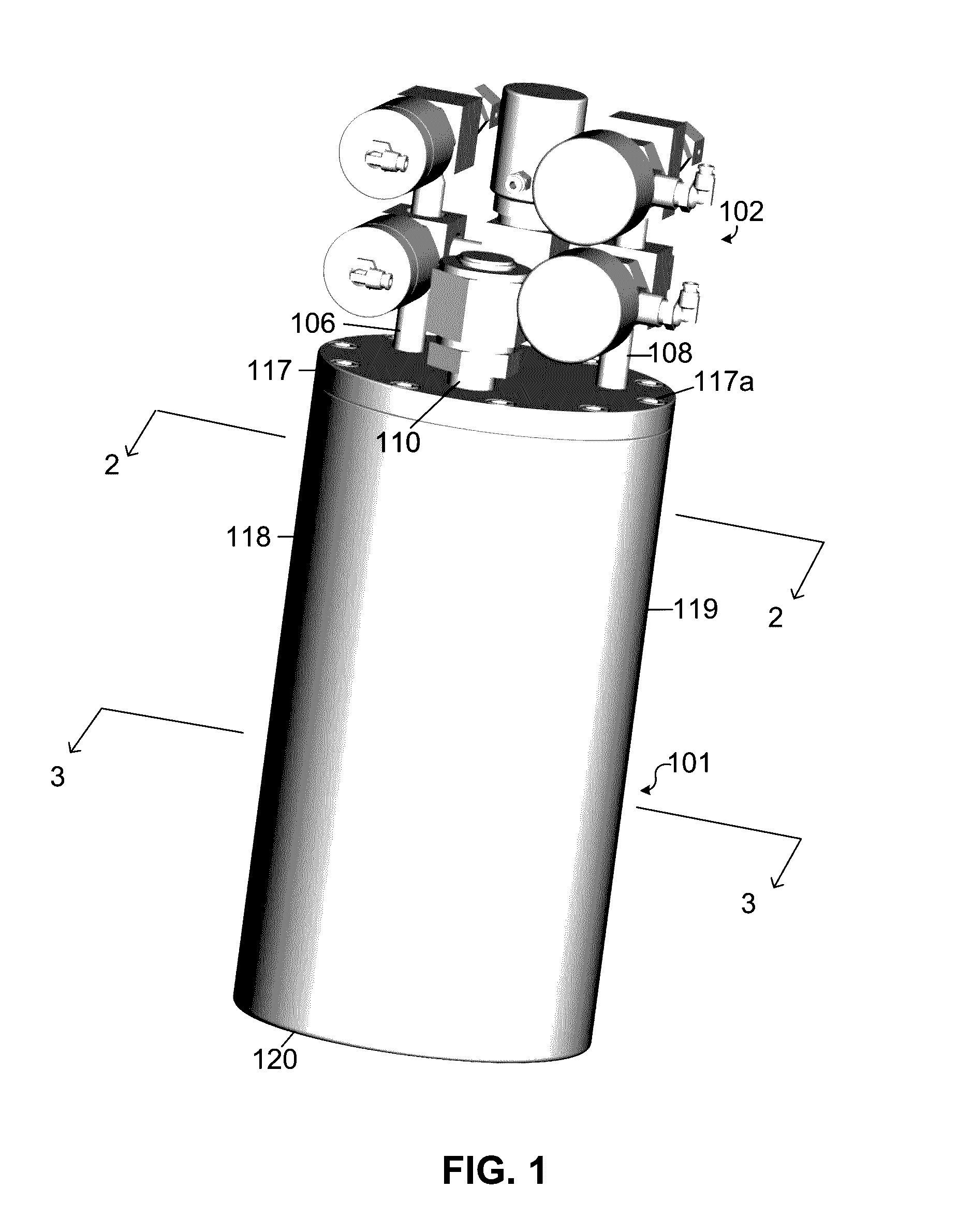
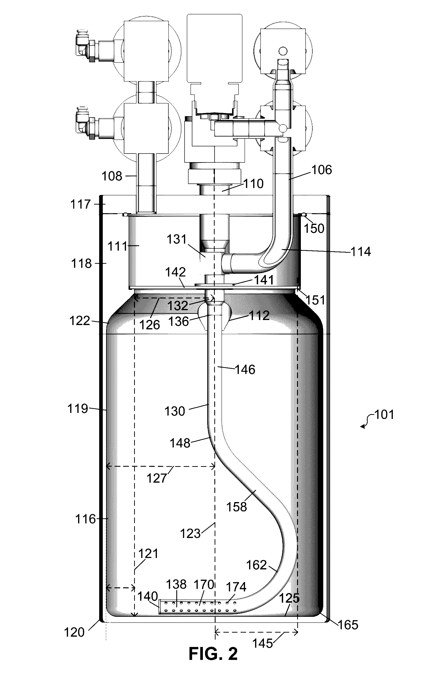
[0098]In order to demonstrate the advantages of the present invention, two tests were performed. Test 1 was performed using the vessel 101 shown in FIGS. 1-4, which includes on the curved diffuser tube 130 having a plurality of the nozzle openings 174 (see, e.g., FIG. 2). Test 2 was performed using the prior art vessel described in U.S. Pat. No. 9,109,287, which is hereby incorporated by reference as if fully set forth. The prior art vessel has an inlet port that terminates above the separator 142 (i.e., the diffuser tube 130 is not provided), but is otherwise identical to the vessel 101 shown in FIGS. 1-4. This results in carrier gas being introduced into the lower portion of the container only above the separator 142.

[0099]Both of the tests were performed by introducing one kilogram of solid precursor tantalum chloride (TaCl5) into the vessel, then placing the vessel in an oven heated to 90 degrees Celsius on an aluminum plate maintained at 80 degrees Celsius. This temperature gra...


PUM

PropertyMeasurementUnit
Fractionaaaaaaaaaa
Efficiencyaaaaaaaaaa
Particle sizeaaaaaaaaaa

Abstract

A vessel for conveying a precursor-containing fluid stream from a precursor material contained within the vessel using a carrier gas. The vessel defines an interior volume segmented into an upper volume and a lower volume, the upper volume being in fluid communication with the lower volume, the lower volume containing substantially all of the precursor material and being separated from the upper volume by a separator. The vessel includes a diffuser tube that extends from an inlet port, through the separator and has a distal end having a plurality of openings formed therein and extends along the bottom interior wall of the vessel.

Description

CROSS REFERENCE TO RELATED PATENT APPLICATIONS[0001]The present patent application claims the benefit of U.S. Provisional Patent Application Ser. No. 62 / 149,548 filed Apr. 18, 2015.BACKGROUND[0002]The electronic device fabrication industry requires various chemicals as raw materials or precursors to fabricate integrated circuits and other electronic devices. Deposition processes such as, chemical vapor deposition (CVD) and atomic layer deposition (ALD) processes, are used in one or more steps during the manufacture of a semiconductor device to form one or more films or coatings on the surface of a substrate. In a typical CVD or ALD process, a precursor source that may be in a solid and / or liquid phase is conveyed to a reaction chamber having one of more substrates contained therein where the precursor reacts under certain conditions such as temperature or pressure to form the coating or film on the substrate surface.[0003]There are several accepted technologies to supply a precursor...

Claims


Application Information

Patent Timeline
IPC IPC(8): C23C16/448C23C16/455
CPCC23C16/45561C23C16/4481C23C16/08C23C16/16C23C16/18C23C16/45563C23C16/4482C23C16/4483
Inventor BIRTCHER, CHARLES MICHAELSTEIDL, THOMAS ANDREWIVANOV, SERGEI VLADIMIROVICH
Owner VERSUM MATERIALS US LLC
Learn More