Disconnect shaft for an integrated drive generator (IDG)

Active Publication Date: 2016-10-20
HAMILTON SUNDSTRAND CORP
View PDF1 Cites 2 Cited by
  • Summary
  • Abstract
  • Description
  • Claims
  • Application Information

AI Technical Summary

Problems solved by technology

Due to packaging constraints, components of the IDG power gear train must be redesigned.

Method used


Image

  • Disconnect shaft for an integrated drive generator (IDG)
  • Disconnect shaft for an integrated drive generator (IDG)
  • Disconnect shaft for an integrated drive generator (IDG)

Examples


Embodiment Construction

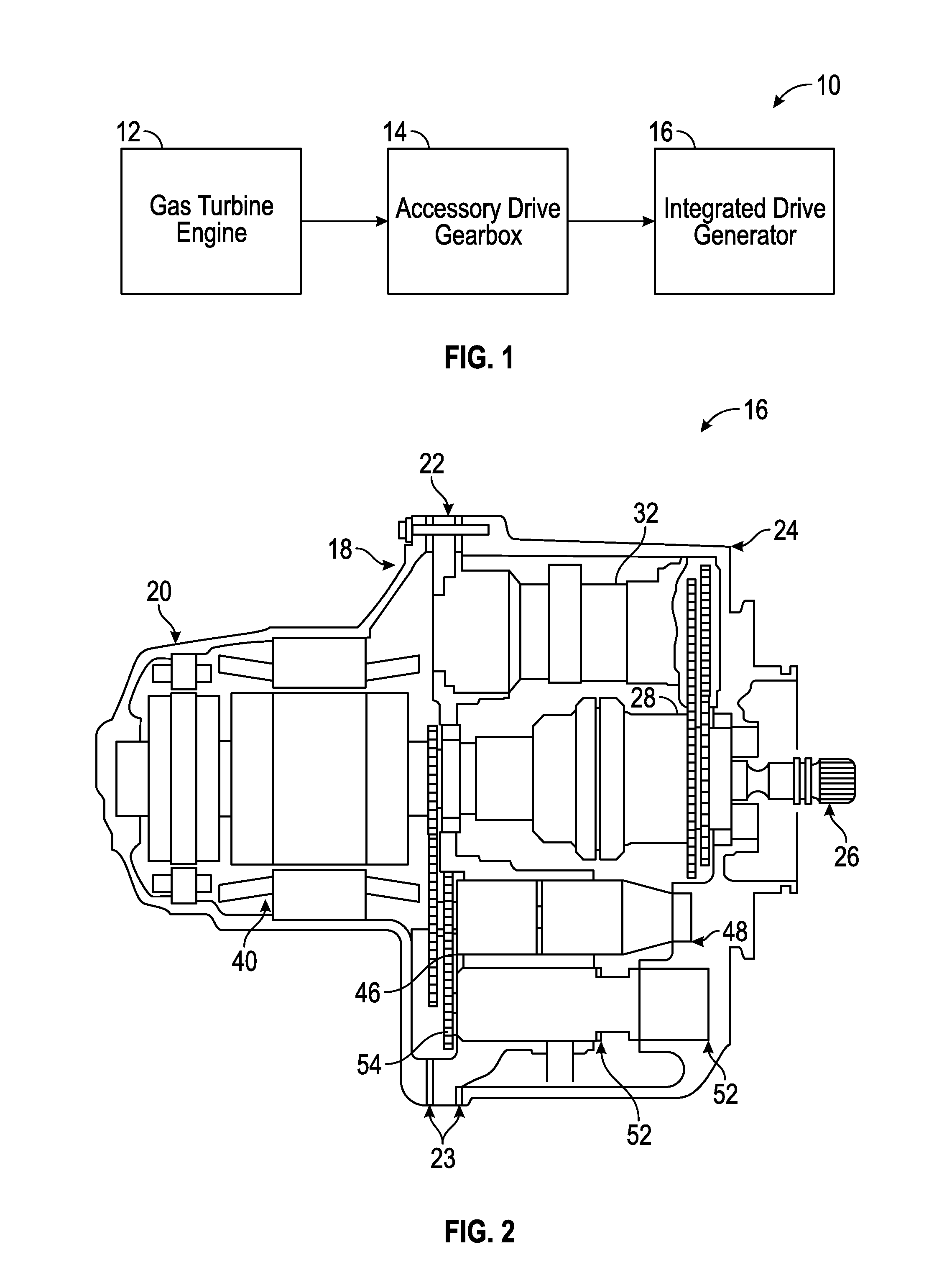
[0019]Referring now to FIG. 1, an example of a generator system 10 is schematically illustrated. The system 10 includes a gas turbine engine 12 that provides rotational drive to an integrated drive generator (IDG) 16 through an accessory drive gearbox 14 mounted on the gas turbine engine 12. The accessory drive gearbox 14 is coupled to a spool of the engine 12, and the speed of the spool varies throughout the entire engine operation.

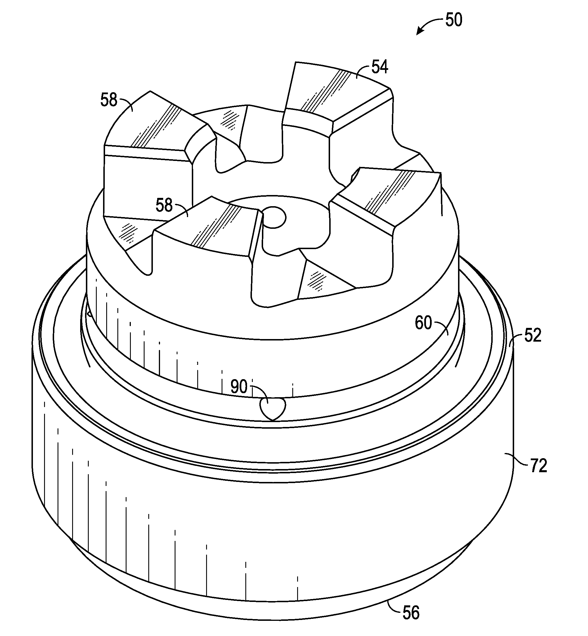
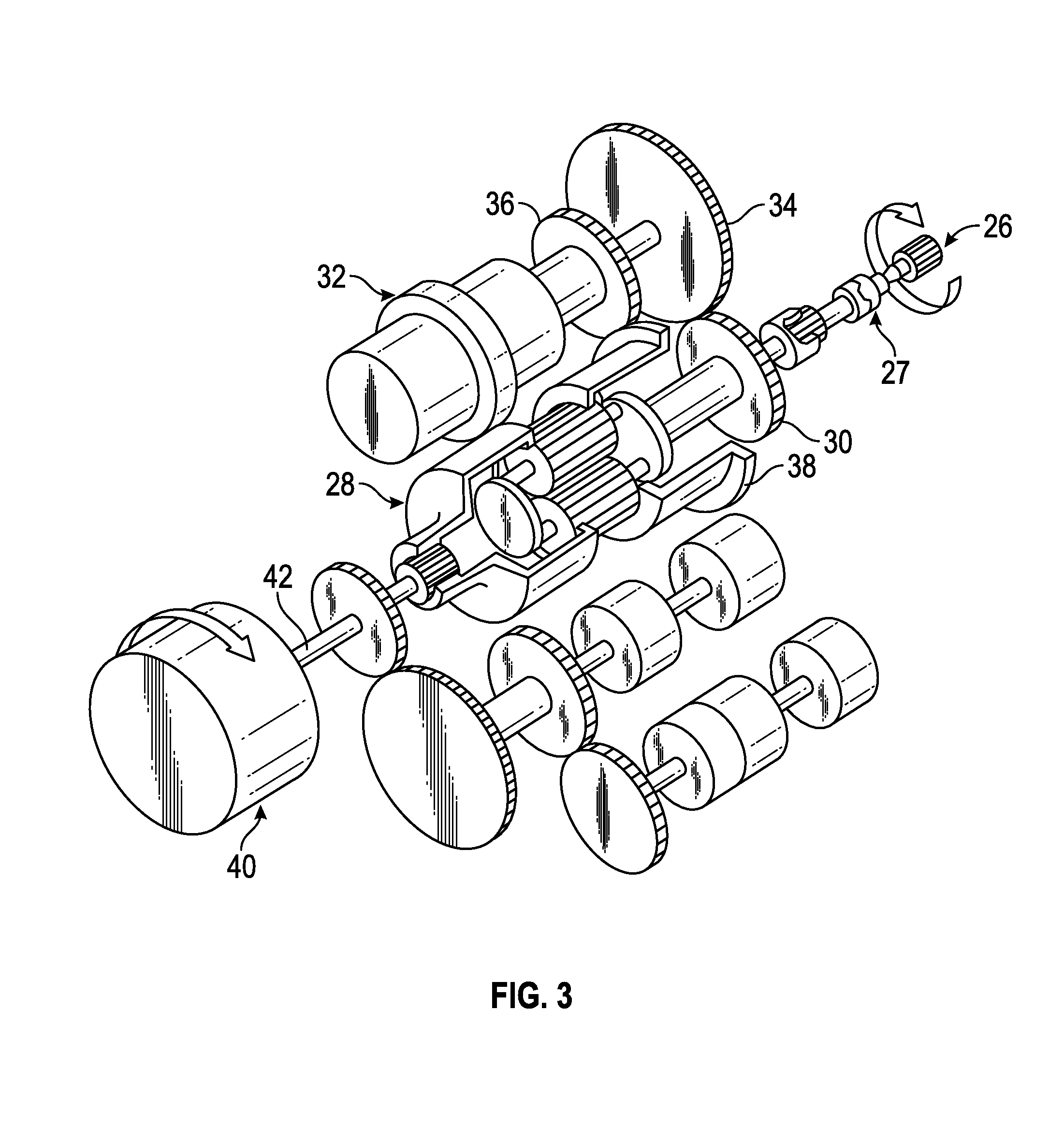
[0020]Referring now to FIGS. 2 and 3, and example of an IDG 16 is illustrated in more detail. As shown, the IDG includes a housing 18 having generator, center, and input housing portion 20, 22, 24 secured to one another. A generator 40 is arranged in the generator housing portion 20. Seal plates 23 are provided on either side of the center housing 22 to seal the center housing 22 relative to the generator and input housing portions 20, 24.

[0021]An input shaft 26 receives rotational drive from the accessory drive gearbox 14. The rotational speed of the in...


PUM


Abstract

A disconnect shaft of an integrated drive generator is provided including a body configured to rotate about an axis of rotation. The body has a first end, a second opposite end, and a plurality of teeth formed adjacent the first end and configured to engage a complementary portion of an adjacent component. A relief is formed in the body such that a first portion is defined between the relief and the plurality of teeth. The first portion includes a plurality of threads having at least one of a major diameter between about 1.3044 and about 1.3125 inches (3.313-3.334 centimeters), a minor diameter between about 1.2482 and about 1.2547 inches (3.170-3.187 centimeters), a pitch diameter between about 1.2765 and about 1.2800 inches (3.242-3.251 centimeters), and a root radius between about 0.0075 and 0.0090 inches (0.0190-0.0029 centimeters).

Description

BACKGROUND OF THE INVENTION[0001]Exemplary embodiments of this invention generally relate to an integrated drive generator, and more particularly, to a disconnect shaft of an integrated drive generator.[0002]Aircrafts currently rely on electrical, pneumatic, and hydraulic systems for secondary power. A typical electrical system utilizes an integrated drive generator (IDG) coupled to each engine to provide a fixed frequency power to the distribution system and loads. One type of IDG includes a generator, a hydraulic unit, and a differential assembly arranged in a common housing. The differential assembly is operably coupled to a gas turbine engine via an input shaft. The rotational speed of the input shaft varies during the operation of the gas turbine engine. The hydraulic unit cooperates with the differential assembly to provide a constant speed to the generator throughout engine operation.[0003]Due to packaging constraints, components of the IDG power gear train must be redesigned...

Claims


Application Information

Patent Timeline
Patent Type & Authority Applications(United States)
IPC IPC(8): F16D11/14
CPCF16D2011/008F16D11/14F16C3/02F16C2360/23F16D1/02
Inventor GROSSKOPF, ANDREW P.FINKE, AARON M.JOHNSON, DUANE C.BEARD, WILLIAM B.
Owner HAMILTON SUNDSTRAND CORP
Why Eureka
Try Eureka