Electrical adjustable table and control method for electrical adjustable table
- Summary
- Abstract
- Description
- Claims
- Application Information
AI Technical Summary
Benefits of technology
Problems solved by technology
Method used
Image
Examples
first embodiment
[0047]Next, please refer to FIG. 4 and FIG. 5. FIG. 5 is a flowchart of a control method of an electrical adjustable table in the first embodiment according to the present invention.
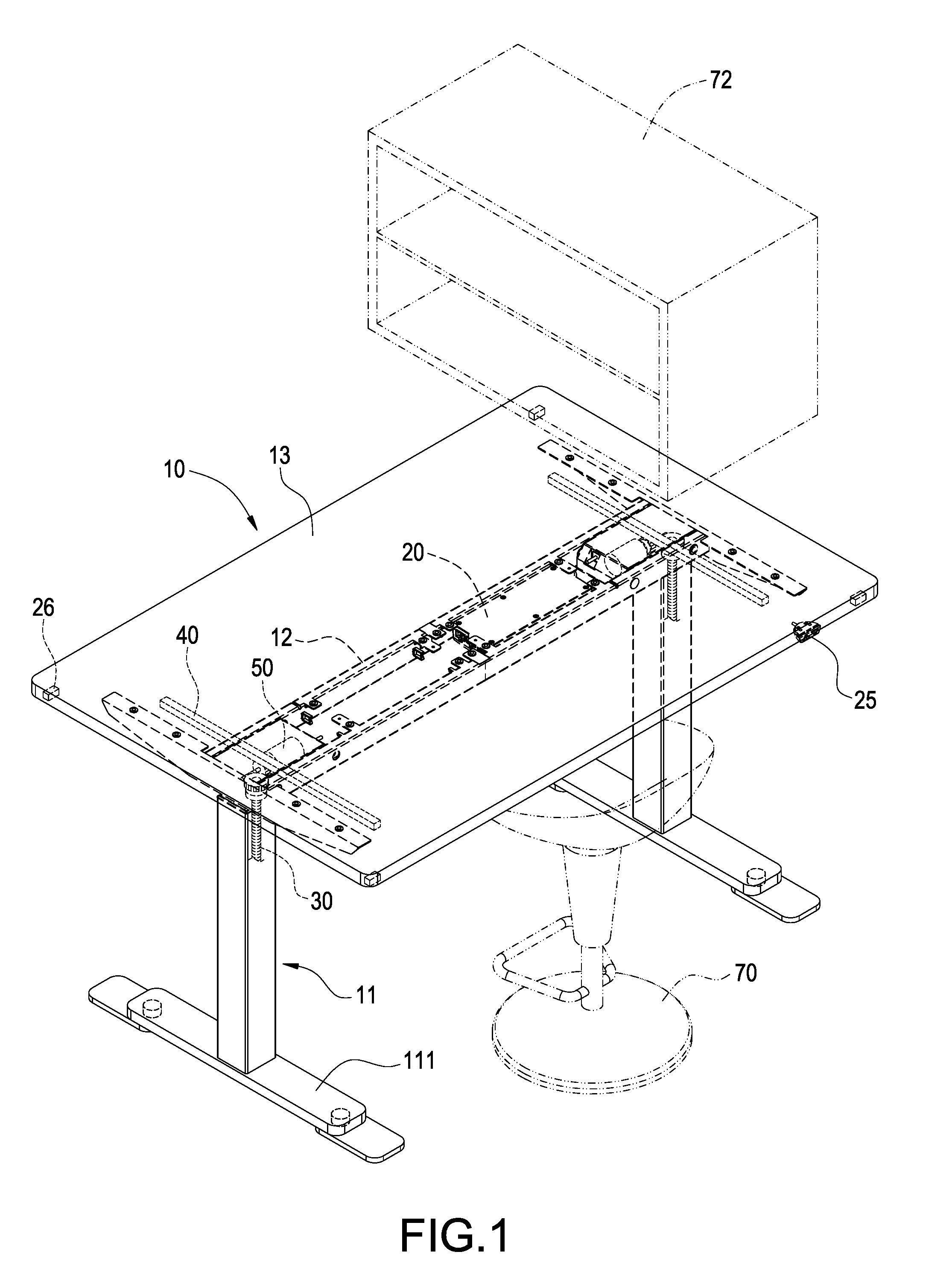
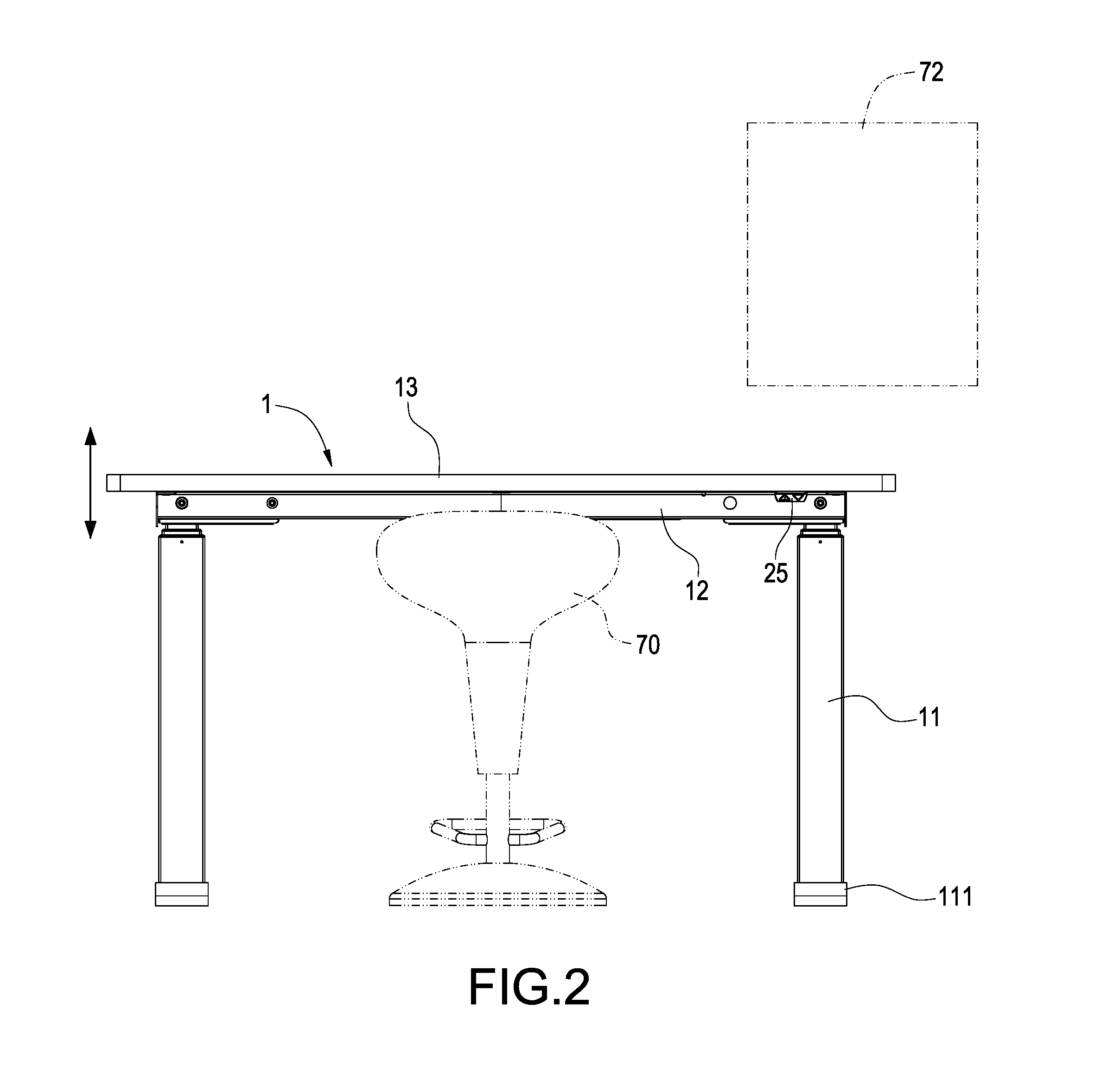
[0048]As illustrated in the drawing, to adjust the height of the electrical adjustable table 10, firstly in step S100, the main control unit 22 in the control box 20 initializes an internal setting value or a user setting value set by a user. Meanwhile, the electrical adjustable table 10 also enters an environment detection mode to detect the obstacles 70, 80.
[0049]In step S102, when entering the environment detection mode, the electrical adjustable table 10 enters the static (standby) mode.
[0050]In step S104, when the electrical adjustable table 10 is in the static mode, the hand control device 25 may receive the operation of a user to generate and transmit a corresponded signal to the main control unit 22 so that the main control unit 22 outputs a corresponded signal to drive the motor 50 to drive the ...
second embodiment
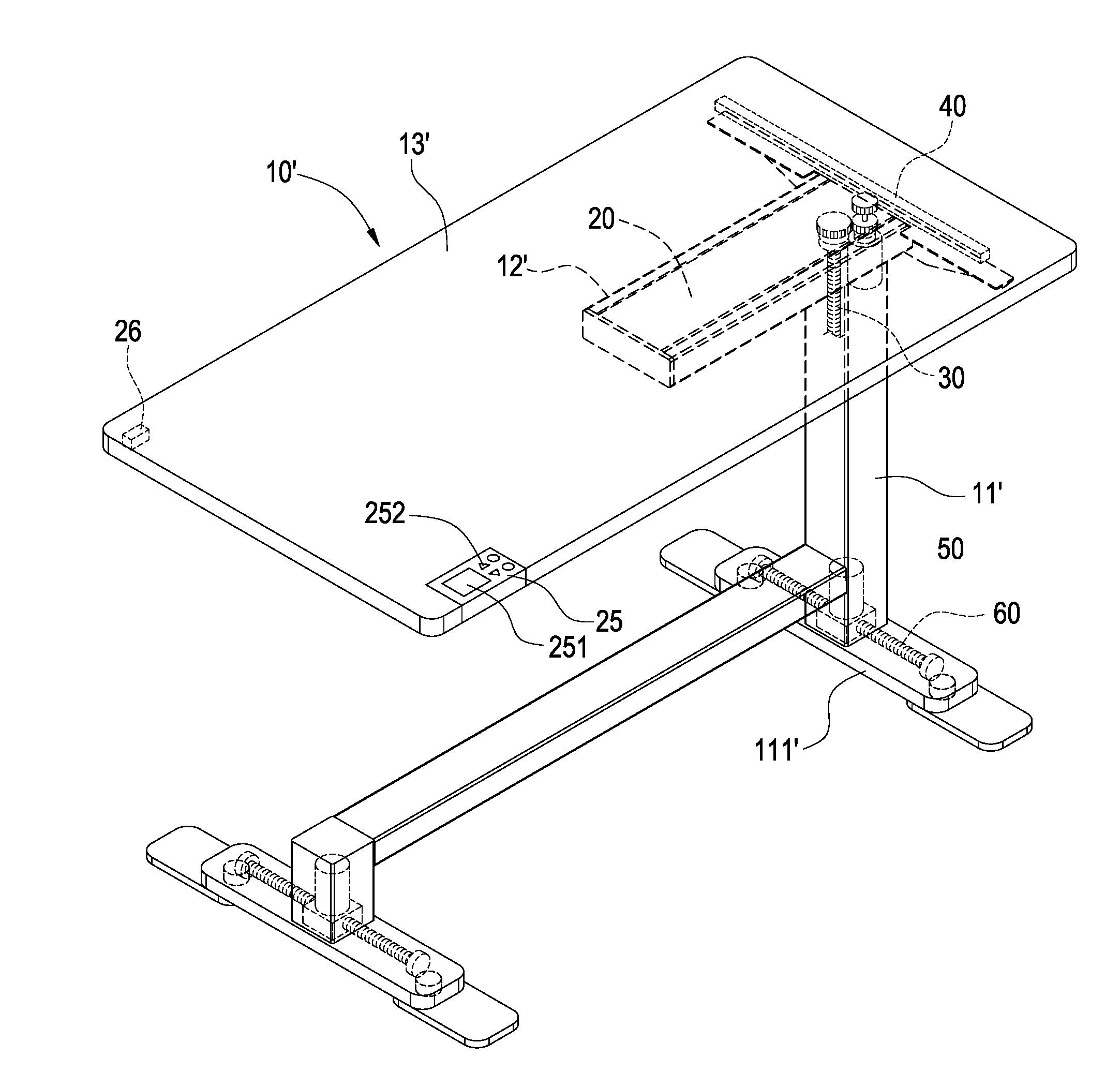
[0064]Please refer to FIG. 6, which is a diagram of an electrical adjustable table of a second embodiment according to the present invention. As illustrated in the drawing, the electrical adjustable table 10′ includes a single table foot 11′. The table foot 11′ has a table foot plate 111′. The table foot 11′ has a beam 12′. A table plate 13′ is disposed on the beam 12′ and the table foot 11′. The control box 20 may be disposed in the beam 12′. The beam 12′ and the table foot 11′are embedded with a lifting structure 30 and the control box 20 may also embedded together with the lifting structure 30 in the table foot 11′. The table plate 13′ is disposed with the motion sensor unit 23. The motion sensor unit 23 may be disposed in the control box 20 or the hand control device 25. The hand control device 25 has at least one touch screen 251 or a button 252. The hand control device 25 may be embedded to the table plate 13′. Besides, the hand control device 25 and the table plate 13′ are at...
third embodiment
[0065]Please refer to FIG. 7, which is a diagram of an electrical adjustable table in a third embodiment according to the present invention. In the embodiment, the touch screen 251 and the button 252 are located at different lateral sides of the hand control device 25. Furthermore, for satisfying ergonomics and user habit, the touch screen 251 and the button 252 may be disposed at the top surface of the hand control device 25 and an adjacent surface that is adjacent to the top surface.
[0066]In the embodiment, the lifting, horizontal movement and control of table foot plate of the electrical adjustable table 10′ are the same as aforementioned embodiment. When the electrical adjustable table 10′is started, the internal setting value or the user setting value are initialized, an environment detection is performed, and the static mode is entered. When the electrical adjustable table 10′ is at static mode, the hand control device 25 may a corresponded signal to the control box 20 accordi...
PUM
 Abstract
Description
Claims
Application Information
 - R&D
- Intellectual Property
- Life Sciences
- Materials
- Tech Scout
- Unparalleled Data Quality
- Higher Quality Content
- 60% Fewer Hallucinations
Browse by: Latest US Patents, China's latest patents, Technical Efficacy Thesaurus, Application Domain, Technology Topic, Popular Technical Reports.
© 2025 PatSnap. All rights reserved.Legal|Privacy policy|Modern Slavery Act Transparency Statement|Sitemap|About US| Contact US: help@patsnap.com


