Drift Compensation for Force Sensing Devices

a technology of force sensing device and drift compensation, which is applied in the calibration/testing of force/torque/work measurement apparatus, measurement device, instruments, etc., can solve the problems of delayed reaction associated with the received force input, the force sensor may not accurately detect the amount of force being applied at a particular time,

Active Publication Date: 2016-10-27
APPLE INC
View PDF1 Cites 5 Cited by
  • Summary
  • Abstract
  • Description
  • Claims
  • Application Information

AI Technical Summary

Problems solved by technology

However, due to different materials used in these force sensors, and more specifically, due to different elastic deformation characteristics of the materials and / or structures, the force sensor may not accurately detect the amount of force being applied at a particular time.
In addition to the above, the elastic deformation of the materials in the force sensor and / or the structure of the force sensor itself, may cause a delayed reaction associated with the received force input.

Method used


Image

  • Drift Compensation for Force Sensing Devices
  • Drift Compensation for Force Sensing Devices
  • Drift Compensation for Force Sensing Devices

Examples


Embodiment Construction

[0016]Various embodiments are described more fully below with reference to the accompanying drawings, which form a part hereof, and which show specific exemplary embodiments. However, embodiments may be implemented in many different forms and should not be construed as limited to the embodiments set forth herein; rather, these embodiments are provided so that this disclosure will be thorough and complete, and will fully convey the scope of the embodiments to those skilled in the art. The following detailed description is, therefore, not to be taken in a limiting sense.

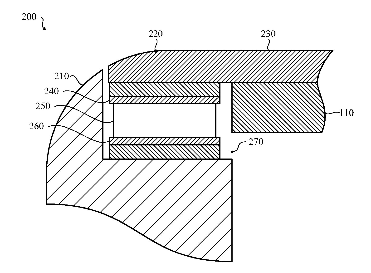
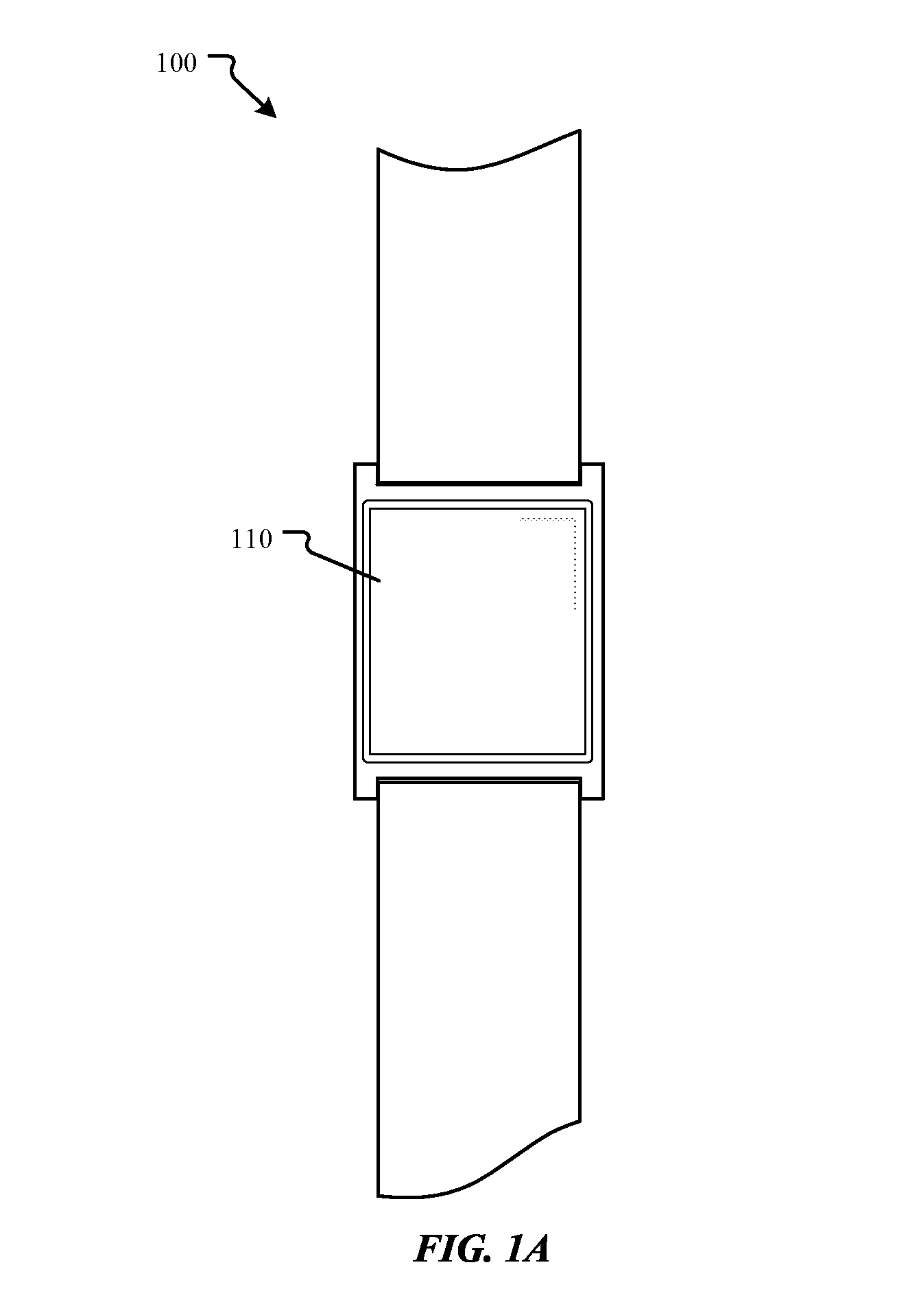
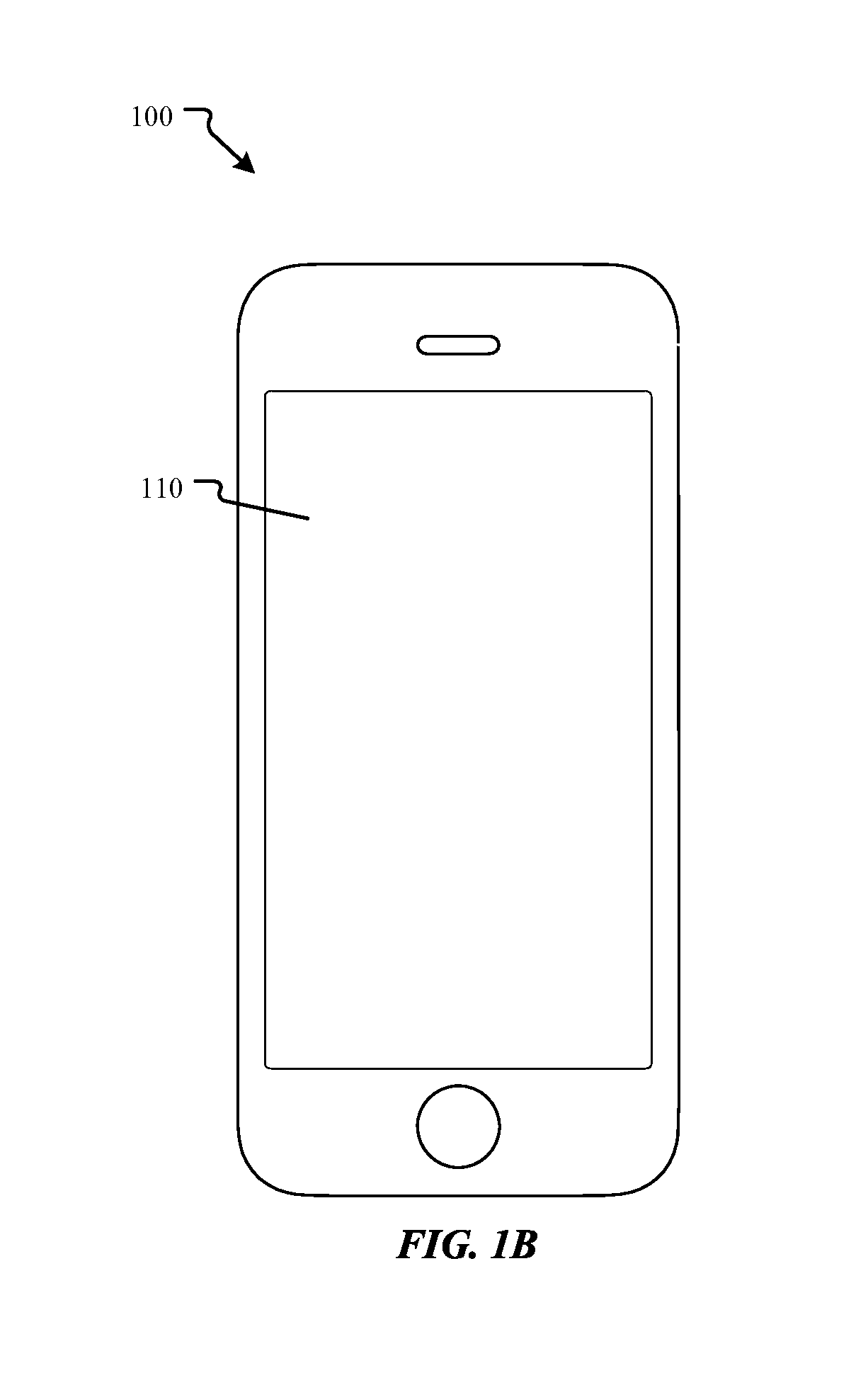
[0017]In some implementations, a computing device, such as those shown in FIGS. 1A-1C, a trackpad for a laptop computer or other input device may use a force sensing device to receive input from a user or an object manipulated by an object (e.g., stylus). The force sensing device may be associated or integrated with a display on the computing device. Further, force received on the display and detected by the force sens...


PUM

PropertyMeasurementUnit
forceaaaaaaaaaa
stabilityaaaaaaaaaa
elastic deformationaaaaaaaaaa

Abstract

Disclosed herein are methods and systems for compensating for drift that may be present in a force sensing device. In some embodiments, the force sensing device may be calibrated to compensate for the drift. The calibration may include receiving an input waveform associated with a received amount of force on the force sensing device. A system model that approximates a transfer function that provides an output waveform associated with the input waveform is then determined. Using the system model, an inverse transfer function associated with the system model is also determined. The inverse transfer function may then be applied to the output waveform which compensates for the drift.

Description

TECHNICAL FIELD[0001]The present disclosure generally relates to force sensing devices. More specifically, the present disclosure is directed to compensating for drift that may occur in force sensing devices such as those used in various computing devices.BACKGROUND[0002]Computing devices may use force sensors to detect a received force. However, due to different materials used in these force sensors, and more specifically, due to different elastic deformation characteristics of the materials and / or structures, the force sensor may not accurately detect the amount of force being applied at a particular time. More specifically, the force sensor may continue to detect that force is being applied to the force sensor even if the force has been removed as it may take some amount of time for the elastomeric material in the force sensor to return to its original (e.g., nominal) position, shape or state. In other cases, the force sensor may continue to detect an increase in force even when ...

Claims


Application Information

Patent Timeline
Patent Type & Authority Applications(United States)
IPC IPC(8): G01L25/00
CPCG01L25/00
Inventor GOWREESUNKER, BABOO V.WESTERMAN, WAYNE C.
Owner APPLE INC
Why Eureka
Try Eureka