Improvements in and relating to waveguides

a waveguide and waveguide technology, applied in the field of waveguides, can solve the problems of difficult to achieve, waveguides are expensive to produce, and misalignment of light outpu

Active Publication Date: 2016-11-03
BAE SYSTEMS PLC
View PDF1 Cites 96 Cited by
  • Summary
  • Abstract
  • Description
  • Claims
  • Application Information

AI Technical Summary

Benefits of technology

[0048]A periodic perturbation or variation of the refractive index of the waveguide part or surface corrugation upon it, may define a diffraction grating and this has the effect of changing the impulsion (wave vector surf

Problems solved by technology

A misalignment between the orientation of grating lines in the first (input) grating and the second grating will result in a misalignment of light output from the se

Method used


Image

  • Improvements in and relating to waveguides
  • Improvements in and relating to waveguides
  • Improvements in and relating to waveguides

Examples


Embodiment Construction

[0061]In the drawings like reference symbols refer to like items.

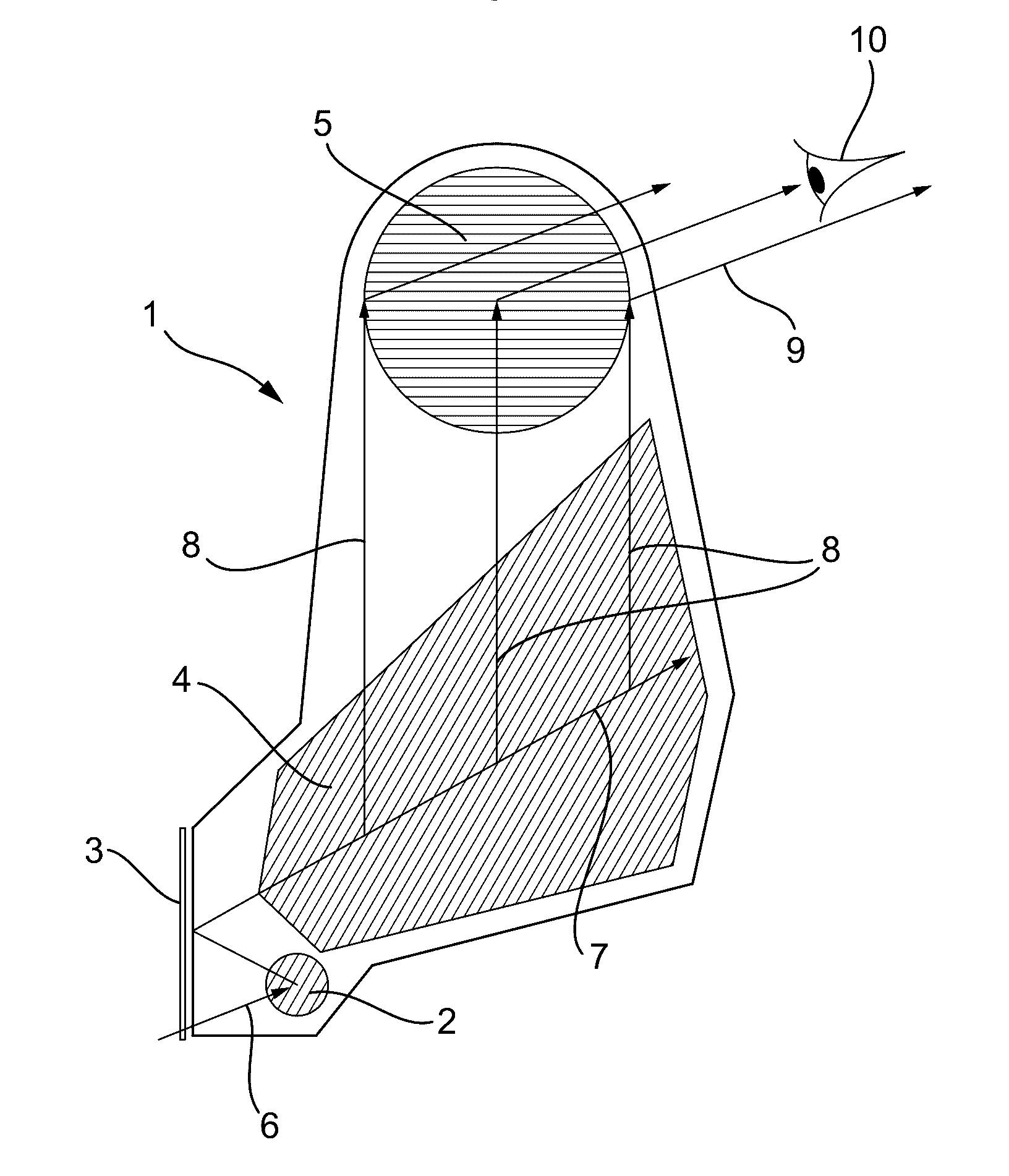
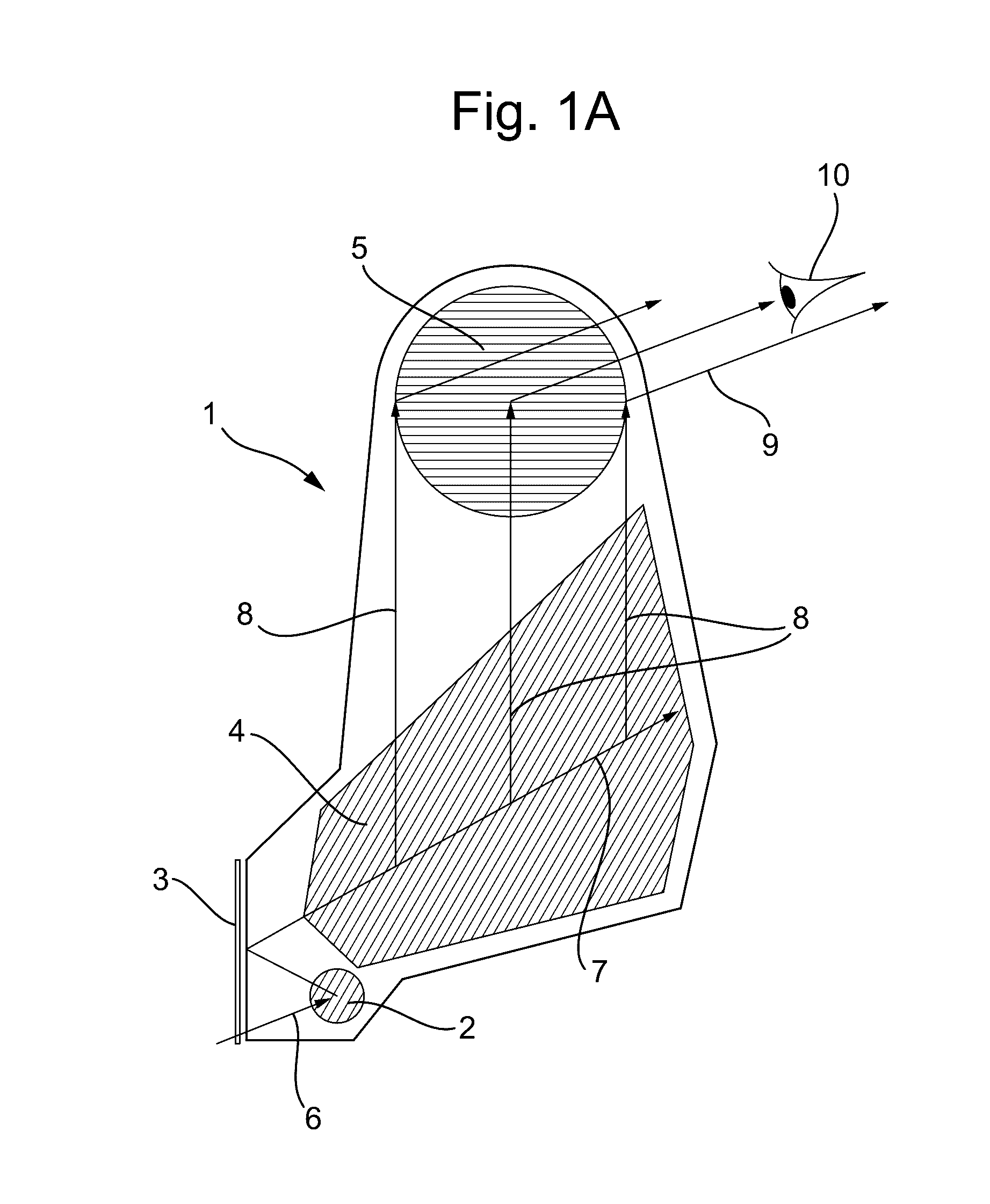
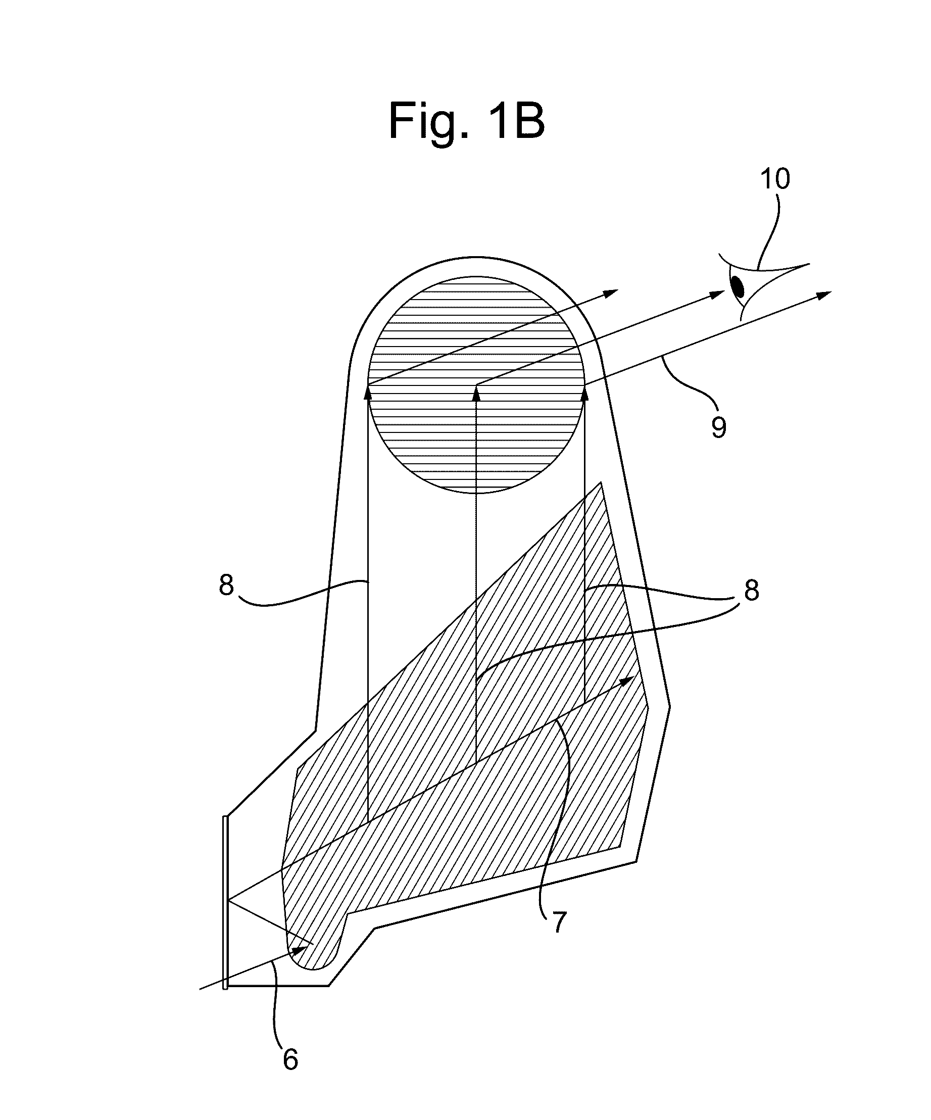
[0062]FIG. 1A shows a prior art waveguide for a display apparatus. The waveguide comprises a slab optical waveguide 1 for guiding light internally by total internal reflection between two opposing parallel and planar surfaces of the slab.

[0063]Image-bearing light to be displayed is input to the slab via an input diffraction grating 2 arranged to receive the image-bearing light 6 and to diffract the received light 7 along the slab optical waveguide for guiding across an intermediate diffraction grating 4 optically coupled to the input diffraction grating. The intermediate grating 4 is arranged to expand the received light in a first dimension 7 by diffraction and to direct the expanded light 8 towards an output diffraction grating 5 optically coupled to the intermediate diffraction grating via the slab optical waveguide.

[0064]The output grating is arranged to receive the expanded light 8 from the and to output 9 the rec...


PUM


Abstract

A waveguide for a display apparatus comprising a planar optical waveguide part (20) for guiding light to be displayed, an input diffraction grating (21) to diffract received light (7) along the optical waveguide part for guiding thereby, an intermediate diffraction grating (22) to receive diffracted light from the input diffraction grating and to expand the received light in a first dimension by diffraction (8), and an output diffraction grating (23) to receive the expanded light and to output the received expanded light (10) from the optical waveguide part by diffraction for display. The input diffraction grating is positioned so as to be located wholly within the geographical area of the intermediate grating, and the grating vectors of the input diffraction grating and the intermediate diffraction grating are oriented in different respective directions.

Description

FIELD OF THE INVENTION[0001]The invention relates to a waveguide such as, but without limitation to, an optical waveguide for displays, and to a display device. In particular, the invention is relevant to a display device in which image-bearing light is injected into a waveguide, is expanded to form a visible image and is released from the waveguide for viewing.BACKGROUND[0002]Prior art display devices of this type can comprise a slab waveguide containing three separate diffraction gratings arranged to perform a respective one of three successive functions. A first grating serves as a light input area for diffracting received light in a direction along the slab waveguide. A second grating serves to expand the light from the first grating in a first dimension, and a third grating serves to receive the expanded light and further expand the light in a second dimension orthogonal to the first dimension and to output the result from the waveguide. In order that the second diffraction gra...

Claims


Application Information

Patent Timeline
IPC IPC(8): G02B5/18F21V8/00G02B27/42G02B27/01
CPCG02B5/1823G02B27/0172G02B2027/0125G02B6/0035G02B27/4272G02B6/0016G02B27/0081G02B6/34
Inventor SIMMONDS, MICHAEL DAVIDFERNS, ANTHONY ROBERT
Owner BAE SYSTEMS PLC
Why Eureka
Try Eureka