Ultrafast electromechanical disconnect switch

a technology of electromechanical disconnect switch and mechanical switch, which is applied in the direction of magnetostrictive relay, high-tension/heavy-dress switch, electrical apparatus, etc., can solve the problems of power electronics switch significant conduction loss, propellant-based system cannot be automatically reset, and each of the foregoing is flawed, so as to achieve ultra-fast voltage withstand capability

Active Publication Date: 2016-11-10
FLORIDA STATE UNIV RES FOUND INC
View PDF12 Cites 5 Cited by
  • Summary
  • Abstract
  • Description
  • Claims
  • Application Information

AI Technical Summary

Benefits of technology

[0027]An object of the present invention is to use a vacuum or pressurized gas chamber with internal actuator-driven contacts for an electrical switch that can provide ul...

Problems solved by technology

However, each of the foregoing is flawed.
Thomson coils require high current pulses, power electronics switches have significant conduction losses, propellant based systems cannot be automatically reset, and coupled electromechanical and hydraulic systems can be complex and slow.
One of the drawbacks of these methods is the f...

Method used


Image

  • Ultrafast electromechanical disconnect switch
  • Ultrafast electromechanical disconnect switch
  • Ultrafast electromechanical disconnect switch

Examples


example 1

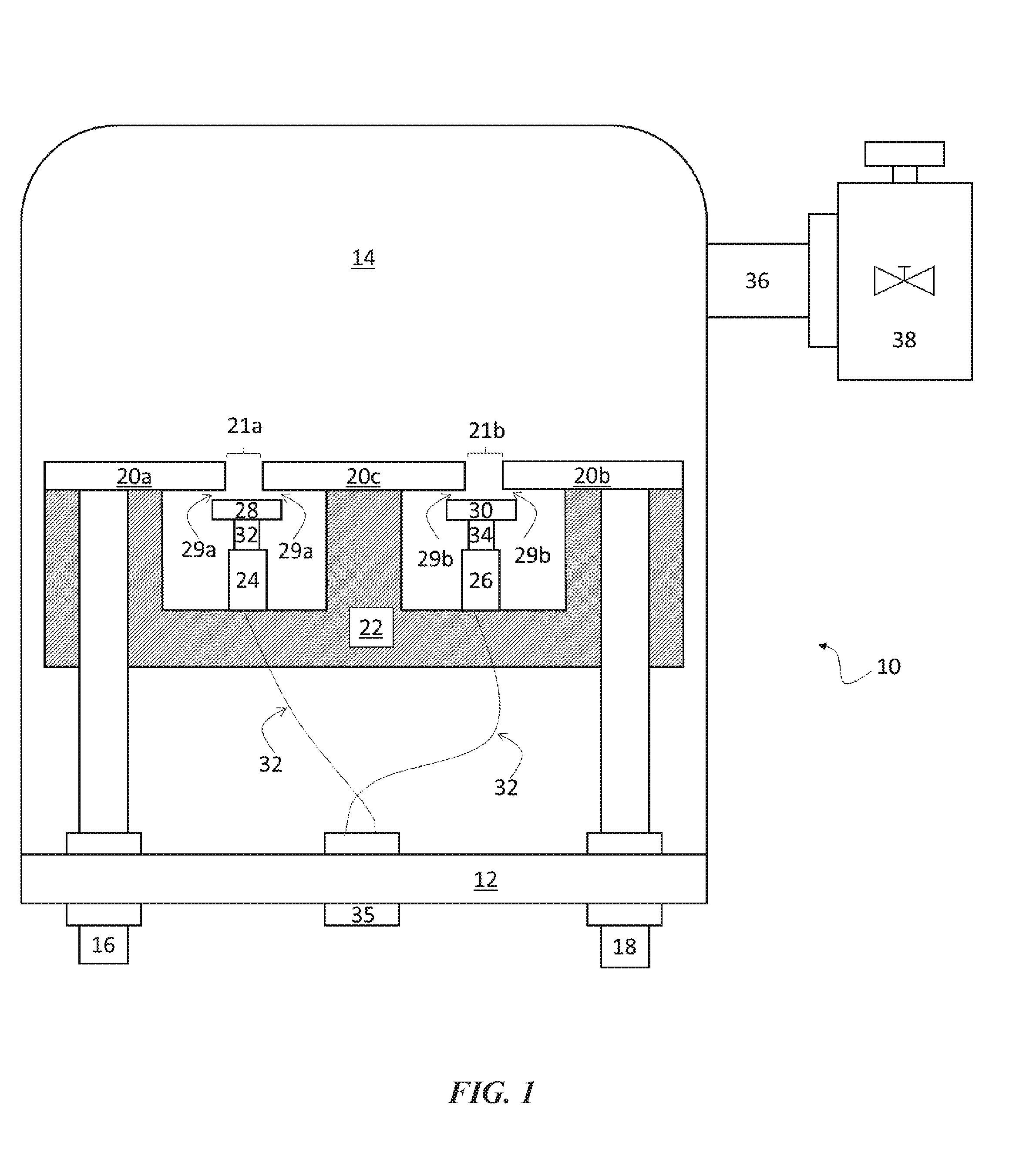
[0042]In an embodiment, as shown in FIG. 1, the current invention is a switching mechanism, generally denoted by the reference numeral 10, that includes an enclosed switching chamber created with the use of flange (12) and vessel (14). Electrical feedthroughs (16, 18) pass through flange (12) into the switching chamber. On the outside of the switching chamber, the conductors (not shown in this figure) that pass through feedthroughs (16, 18) are used to connect to the two electrical poles of the system that will be separated by the disconnect. Inside the switching chamber, feedthroughs (16, 18) connect to non-movable electrical contacts (20a, 20b), once feedthroughs (16, 18) have passed through the block of insulating material (22). Insulating material (22) serves to electrically insulate switching mechanism (10) from the surrounding walls of vessel (14) and flange (12). Non-movable contact (20c) is coupled to insulating material (22) and is positioned between non-movable contacts (2...

example 2

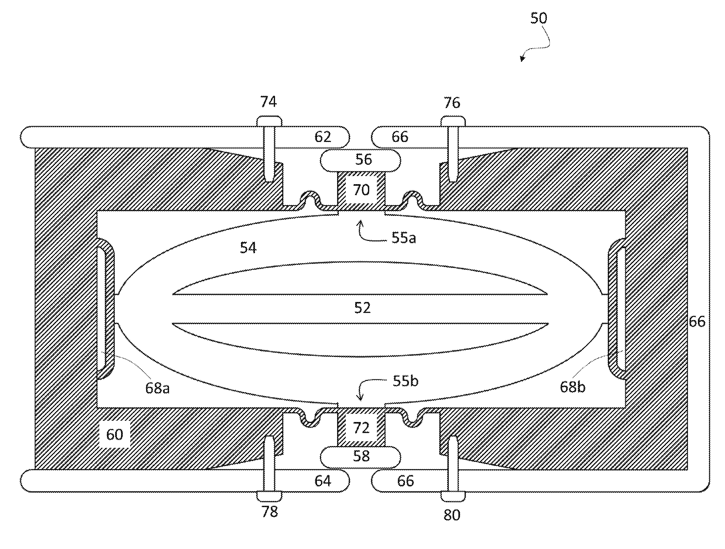
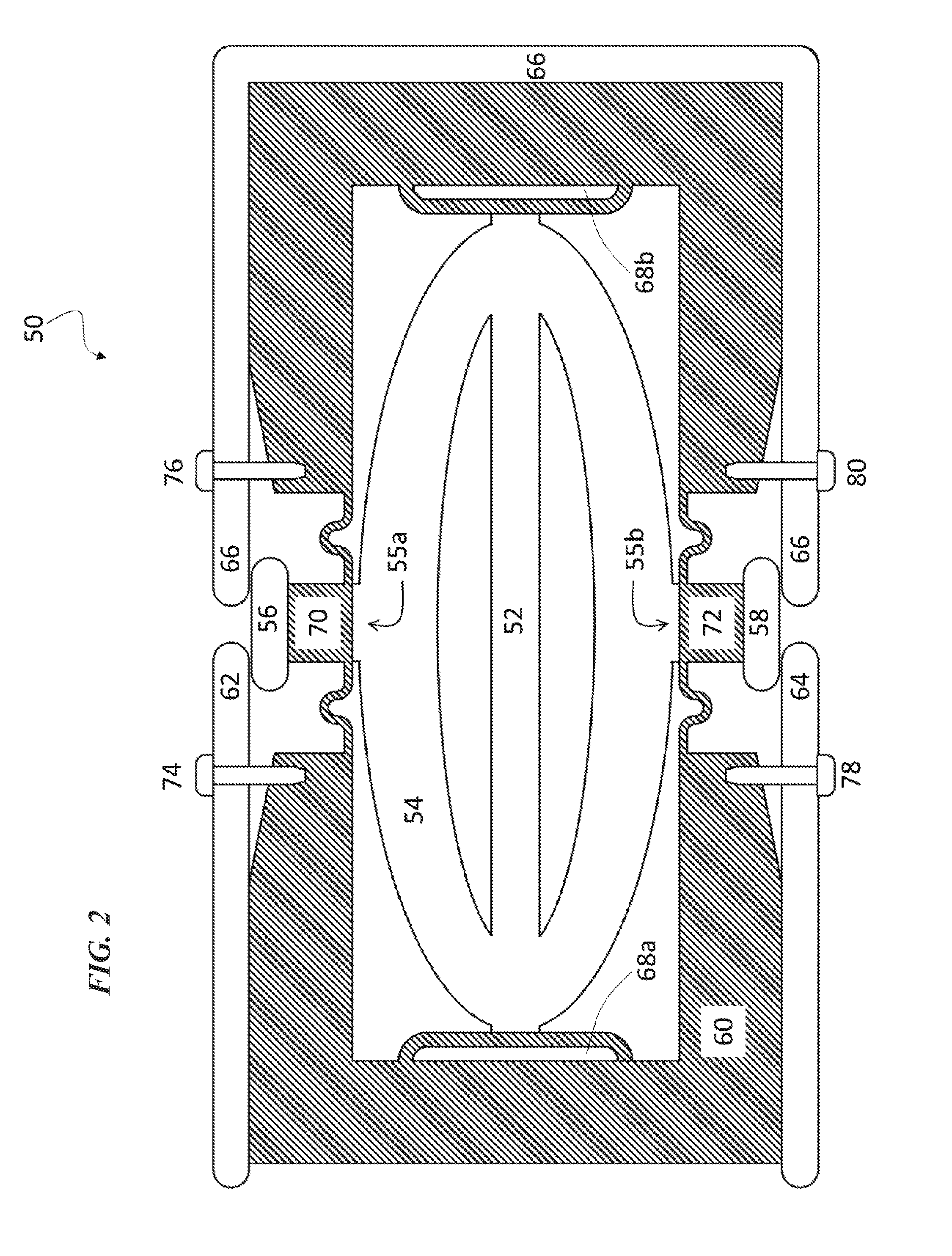
[0050]FIGS. 2-4 depict an alternate embodiment of the current invention, generally denoted by the reference numeral 50. Switching mechanism 50 can be based on the use of piezoelectric actuator (52) with elliptical shell (54) outside of piezoelectric actuator (52). The planar geometry allows for series and parallel connections to increase voltage withstand and current ratings with only minimum increase in size.

[0051]Elliptical shell actuator (54) can be used to drive (i.e., open and close) movable contacts (56, 58) of switching mechanism (50) on each side of elliptical shell (54) in a very fast manner, while still providing enough contact pressure for low ohmic contact resistance in closed state. At the same time, elliptical shell actuator (54) also allows for high voltage withstand capability in open state.

[0052]Movable contacts (56, 58) can be characterized as follows:

[0053]No electric arcs→little contact wear expected

[0054]Vacuum is benign environment→no oxidation, i.e., use of re...


PUM


Abstract

An ultrafast electrical (e.g., transfer, disconnect, etc.) switch that is simple, compact, does not require high energy to operate, ultralow loss, clean, and capable of being automatically reset. The invention includes a fast electromechanical switch having a drive mechanism integrated into the switching chamber. The integration of the drive mechanism into the switching chamber provides faster contact travel and therefore a faster switching operation. Additionally, the switching chamber is a self-contained environment that may consist of a high-pressure gas or a vacuum. The invention further includes an ultrafast disconnect switch. The invention generally is an integrated piezoelectric-actuator-based mechanical switching mechanism. The mechanism has a central piezoelectric actuator that extends to pull contacts inwards in order to obtain two disconnects within a millisecond or less. Surrounding the piezoelectric actuator is a polymer insulating shell and beyond the shell is the metallic conductor.

Description

CROSS-REFERENCE TO RELATED APPLICATIONS[0001]This nonprovisional application is a continuation of and claims priority to International Patent Application No. PCT / US2015 / 012583, entitled Ultrafast Electromechanical Disconnect Switch”, filed Jan. 23, 2015 by the same inventors, which claims priority to U.S. Provisional Application No. 61 / 930,755, entitled “Fast Electrochemical Disconnect Switching Chamber with Integrated Drive Mechanism”, filed Jan. 23, 2014 by the same inventors, and to U.S. Provisional Application No. 62 / 033,454, entitled “Ultrafast Disconnect Switch”, filed Aug. 5, 2014 by the same inventors, all of which are incorporated herein by reference in their entireties.FEDERALLY SPONSORED RESEARCH OR DEVELOPMENT[0002]This invention was made with Government support under Grant No. EEC0812121 awarded by National Science Foundation. The government has certain rights in the invention.BACKGROUND OF THE INVENTION[0003]1. Field of the Invention[0004]This invention relates, genera...

Claims


Application Information

Patent Timeline
IPC IPC(8): H01H57/00H01H55/00
CPCH01H55/00H01H57/00H01H33/14H01H33/28H01H33/64H01H33/666
Inventor GRABER, LUKASWIDENER, CHRISTOPHERSMITH, SAMANTHASTEURER, MICHAEL
Owner FLORIDA STATE UNIV RES FOUND INC
Why Eureka
Try Eureka