Four-cylinder engine and method of operating four-cylinder engine

a four-cylinder engine and engine technology, applied in the direction of electric control, ignition automatic control, combustion air/fuel air treatment, etc., can solve the problems of non-uniform driving energy per unit time, and discomfort of the occupant of the vehicle equipped with the engine of this kind

Active Publication Date: 2016-11-17
YAMAHA MOTOR CO LTD
View PDF22 Cites 9 Cited by
  • Summary
  • Abstract
  • Description
  • Claims
  • Application Information

AI Technical Summary

Benefits of technology

[0011]eliminate the problems described above, and provide a four-cylinder engine which causes unequal-interval explosions but produces little or no change in the driving energy per unit time during an operating state in which an occupant tends to feel torque fluctuations, and a method of operating the four-cylinder engine.
[0015]Consequently, the magnitude of torque generated in at least one of the two cylinders having an explosion interval of 90° as a crank angle becomes smaller than those of torques generated in the other two cylinders. This prevents or significantly reduces the phenomenon in which the driving energy becomes higher in a portion of one cycle than in other portions because torques are successively generated within a short time. Accordingly, preferred embodiments of the present invention provide a four-cylinder engine that uniformly provides the driving energy of the engine, and a method of operating the four-cylinder engine.
[0018]As described above, the four-cylinder engine and the method of operating the four-cylinder engine enables an occupant to experience, e.g., the same vibrations and torque fluctuations as those of a three-cylinder engine in which explosion intervals are not so different. A three-cylinder engine in which explosions occur at equal intervals gives no sense of discomfort to an occupant of a vehicle equipped with this engine.

Problems solved by technology

A four-cylinder engine in which the explosion intervals are 270°, 180°, 90°, and 180° as crank angles poses a problem when the engine speed is low.
This problem is that an occupant of a vehicle equipped with the engine of this kind feels a sense of discomfort.
The main cause of this sense of discomfort is that the explosion intervals of the four cylinders are unequal so the driving energy per unit time becomes non-uniform.
That is, since the torque is generated in succession within a short time as described above, the driving energy rises in a portion of one cycle, so the driving energy per unit time becomes non-uniform as described above.
Consequently, the occupant experiences an irregular torque change when the engine speed is low, and feels a sense of discomfort.

Method used


Image

  • Four-cylinder engine and method of operating four-cylinder engine
  • Four-cylinder engine and method of operating four-cylinder engine
  • Four-cylinder engine and method of operating four-cylinder engine

Examples


first preferred embodiment

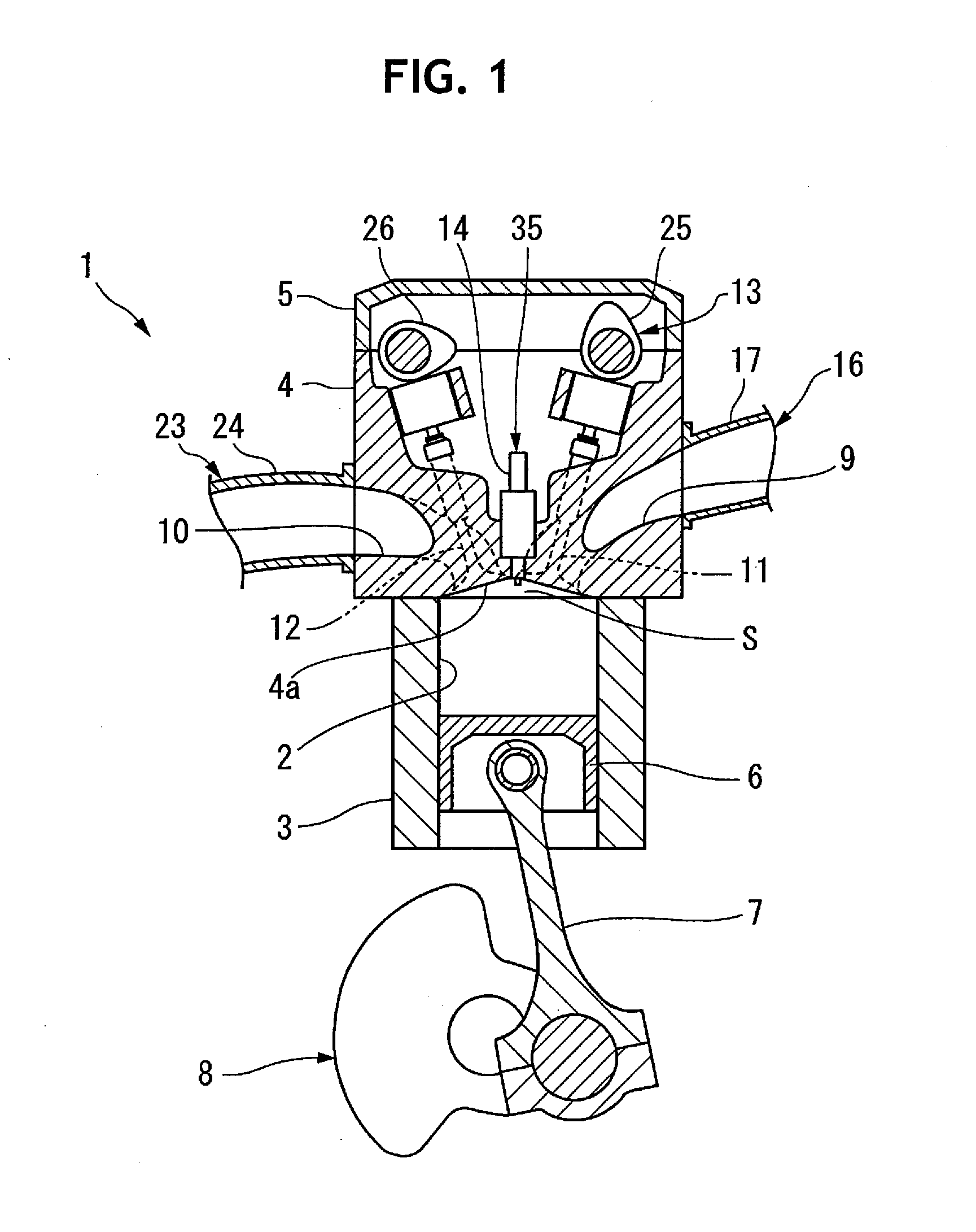
[0049]A first preferred embodiment of a four-cylinder engine and a method of operating the four-cylinder engine will be explained in detail below with reference to FIGS. 1 to 9.

[0050]A four-cylinder engine 1 shown in FIG. 1 preferably is a 4-stroke inline four-cylinder engine or 4-stroke parallel four-cylinder engine to be mounted in a vehicle (not shown), for example. FIG. 1 depicts only the main constituent elements of the four-cylinder engine 1. As shown in FIG. 1, the four-cylinder engine 1 includes a cylinder body 3 including four cylinder holes 2, a cylinder head 4 attached to the cylinder body 3, and a head cover 5 attached to the cylinder head 4.

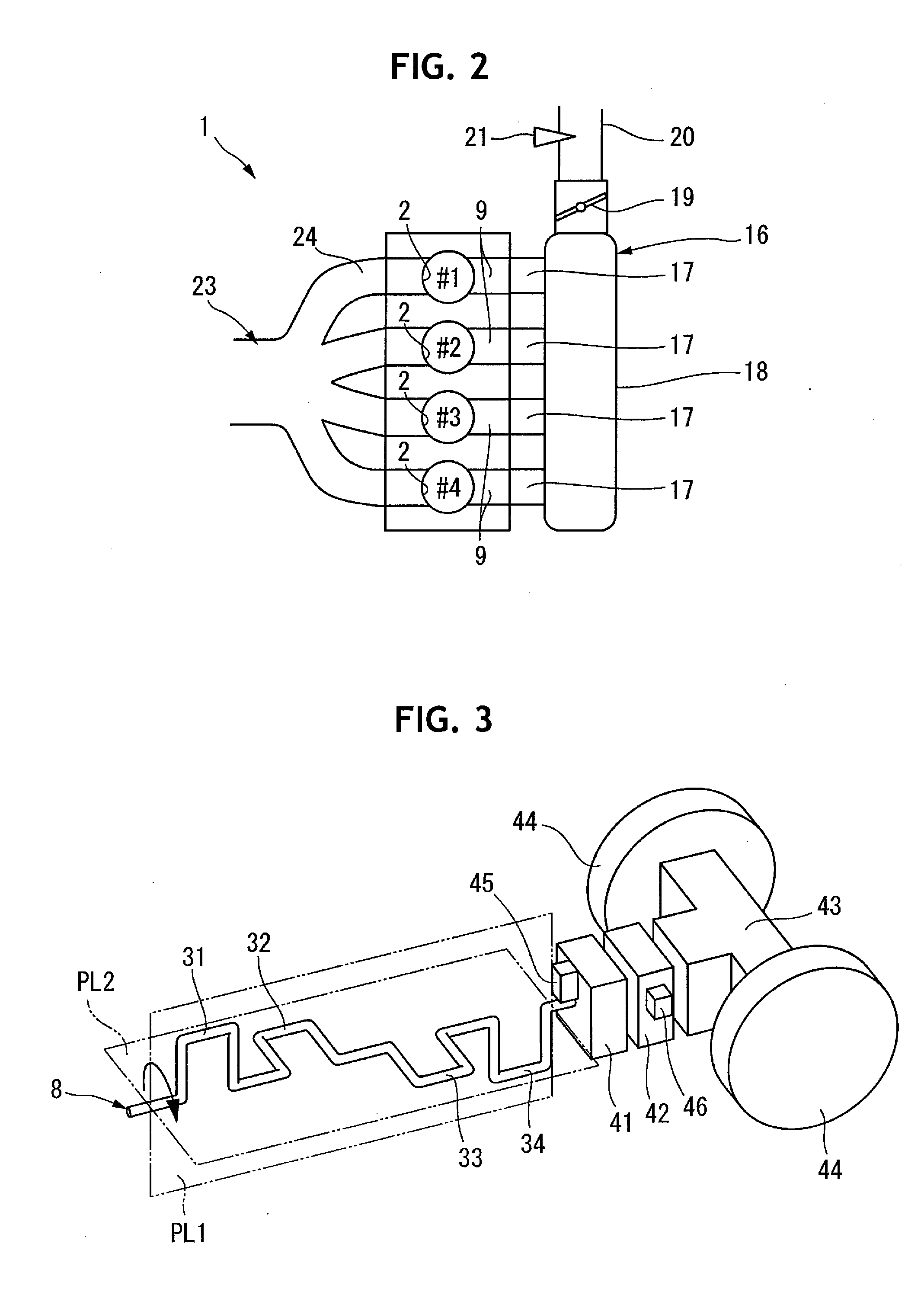
[0051]As shown in FIG. 2, the four cylinder holes 2 are provided in the cylinder body 3 to extend along a line in the radial direction. The four-cylinder engine includes first to fourth cylinders including the four cylinder holes 2. In FIG. 2, reference symbols #1, #2, #3, and #4 respectively denote the first, second, third, and four...

second preferred embodiment

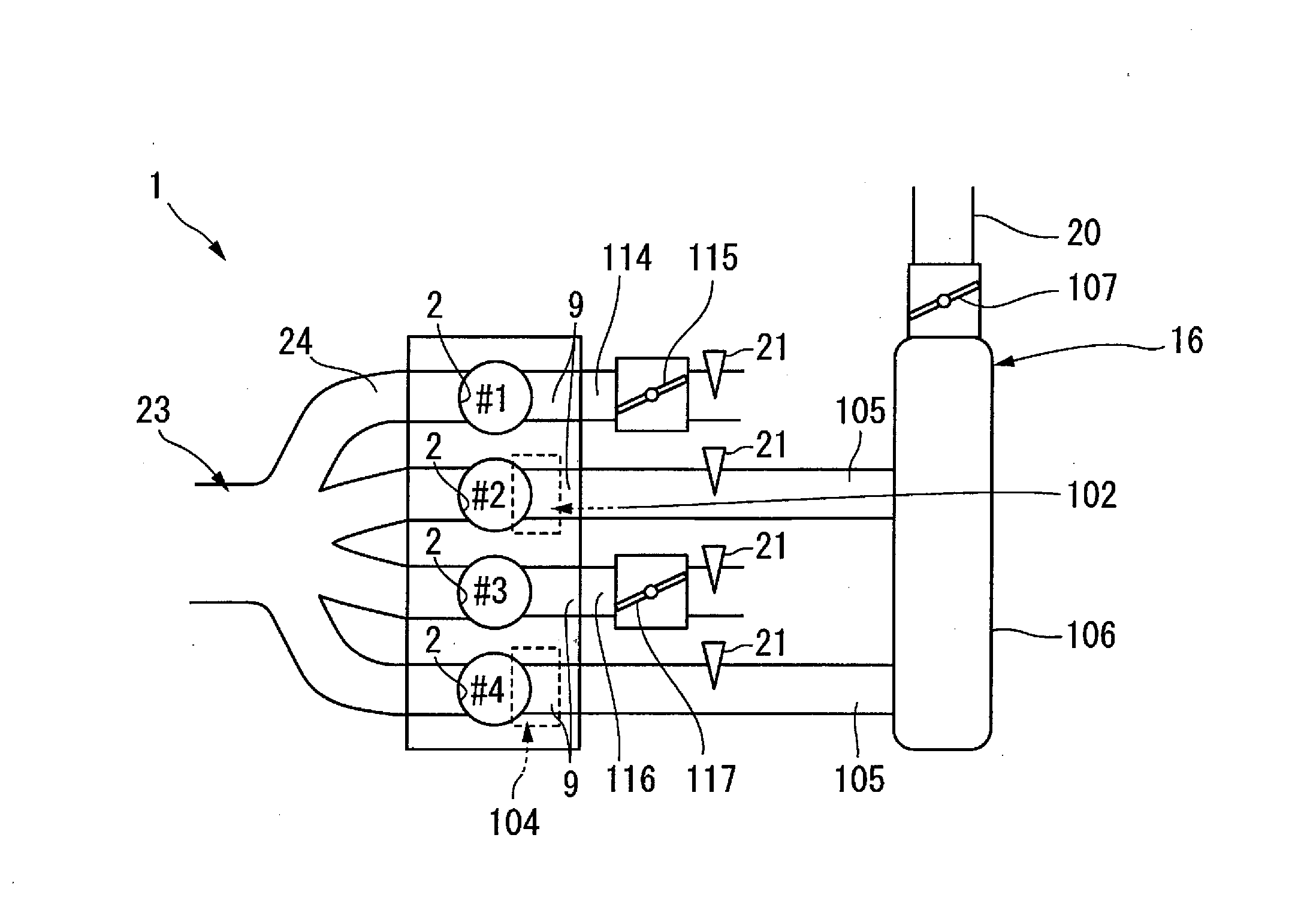
[0094]As shown in FIGS. 10 to 13, the indicated mean effective pressures of two cylinders having an explosion interval of 90° may also be decreased by using an intake device. The same reference numerals as in FIGS. 1 to 9 denote the same or similar members in FIGS. 10 to 13, and a detailed explanation thereof will properly be omitted.

[0095]The differences of a four-cylinder engine 1 shown in FIG. 10 from the four-cylinder engine when using the first preferred embodiment shown in FIGS. 1 to 9 are the configuration of an ignition system and an intake device 16, and the rest of the arrangements are the same. As will be described below, the ignition system of the four-cylinder engine 1 according to the present preferred embodiment improves or optimizes the ignition timings of all cylinders by producing differences between the intake air volumes of the cylinders. The present preferred embodiment does not perform retard control as explained in the above-described first preferred embodimen...

third preferred embodiment

[0114]As shown in FIGS. 16 to 19, the indicated mean effective pressures of two cylinders having an explosion interval of 90° may be decreased by using an intake device. The same reference numerals as in FIGS. 1 to 15 denote the same or similar members in FIGS. 16 to 19, and a detailed explanation thereof will properly be omitted.

[0115]The differences of a four-cylinder engine 1 shown in FIG. 16 from the four-cylinder engine when using the first preferred embodiment shown in FIGS. 1 to 9 are the configuration of an ignition system and an intake device 16, and the rest of the arrangements are the same. The ignition system of the four-cylinder engine 1 according to the present preferred embodiment improves or optimizes the ignition timings of all cylinders. In the present preferred embodiment, retard control as explained in the above-described first preferred embodiment is not performed.

[0116]The intake device 16 of the four-cylinder engine 1 shown in FIG. 16 includes a first intake d...


PUM


Abstract

An engine includes a cylinder body, a cylinder head, and an ignition device including spark plugs. The engine also includes an intake device connected to intake ports, an exhaust device connected to exhaust ports, pistons, and a crankshaft connected to the pistons by connecting rods. Explosion intervals of the cylinders are 270°, 180°, 90°, and 180° as crank angles. The engine further includes a discomfort eliminator which, when the engine speed is lower than a predetermined value, makes the indicated mean effective pressure of at least one of two cylinders having an explosion interval of 90° lower than the indicated mean effective pressures of the other cylinders having an explosion interval of not 90°. The engine causes unequal-interval explosions but produces little change in the driving energy per unit time during an operating state in which an occupant is liable to feel torque fluctuations.

Description

BACKGROUND OF THE INVENTION[0001]1. Field of the Invention[0002]The present invention relates to a four-cylinder engine in which the explosion intervals of four cylinders are 270°, 180°, 90°, and 180° as crank angles, and a method of operating the four-cylinder engine.[0003]2. Description of the Related Art[0004]As a crankshaft of a four-cylinder engine mounted in a vehicle, a one-plane-type crankshaft (180° crankshaft) in which four crank pins are positioned on one virtual plane and a two-plane-type crankshaft are described in Japanese Patent No. 4533846. Crank pins of the two-plane-type crankshaft are arranged two by two on two virtual planes perpendicular to each other when viewed in the axial direction of the crankshaft.[0005]It is known that a vehicle equipped with a four-cylinder engine using the two-plane-type crankshaft of this kind or a V-type four-cylinder engine including the one-plane-type crankshaft gives an occupant the feeling that an accelerator operation and the beh...

Claims


Application Information

Patent Timeline
Patent Type & Authority Applications(United States)
IPC IPC(8): F02D9/02F02P5/15F02M35/10F02D41/00F02D41/18F02B75/18F02D13/02
CPCF02M35/10386F02B2075/1816F02D2041/001F02D9/02F02B75/18F02M35/10045F02D13/0226F02D41/0002F02D41/008F02D41/18F02P5/1512F02B75/20F02B75/22F02D11/105F02D2200/101F02D2250/28Y02T10/12Y02T10/40
Inventor TSUKAHARA, EITANAKA, DAIJIRO
Owner YAMAHA MOTOR CO LTD
Why Eureka
Try Eureka