Thermal displacement correction training unit for machine tool

a technology of displacement correction and training unit, which is applied in the direction of computer control, program control, instruments, etc., can solve the problems of inconvenient visual determination of the adjustment amount of the correction, the inability to accurately adjust the correction amount, and the slippage of the point at which the work is processed

Active Publication Date: 2016-11-17
FANUC LTD
View PDF0 Cites 3 Cited by
  • Summary
  • Abstract
  • Description
  • Claims
  • Application Information

AI Technical Summary

Benefits of technology

[0015]The present invention can provide a thermal displacement correction training unit for allowing an operator to be trained in order to learn the thermal displacement correction method and the adjustment method for thermal displacement correction of a machine tool without using an actual machine tool.

Problems solved by technology

As a result, the point at which the work is processed slips, which becomes one of the major factors that affect the process precision.
However, the following problems can be cited as problems to be solved in the prior art.
The amount of thermal displacement and the amount of correction thereof are generally minute, which means the amount of adjustment for correction is also minute, and thus, it is difficult to visually determine whether or not the adjustment of the correction amount is precise.
The technology in Japanese Unexamined Patent Publication 2014-54700 does not disclose a method for determining whether or not the adjustment of thermal displacement correction is appropriate.
However, machine tools are generally expensive, which makes it economically difficult to prepare machine tools for the purpose of training for thermal displacement correction.
There is also a risk of affecting other parts of the process in temporarily stopping for training the processing of a work with an actual machine tool that is being used for the processing of a work.
As a result, it is not practical for an operator to have an opportunity to be trained for thermal displacement correction using an actual machine tool.

Method used


Image

  • Thermal displacement correction training unit for machine tool
  • Thermal displacement correction training unit for machine tool
  • Thermal displacement correction training unit for machine tool

Examples


Embodiment Construction

[0020]An embodiment of the present invention is described below in reference to the drawings.

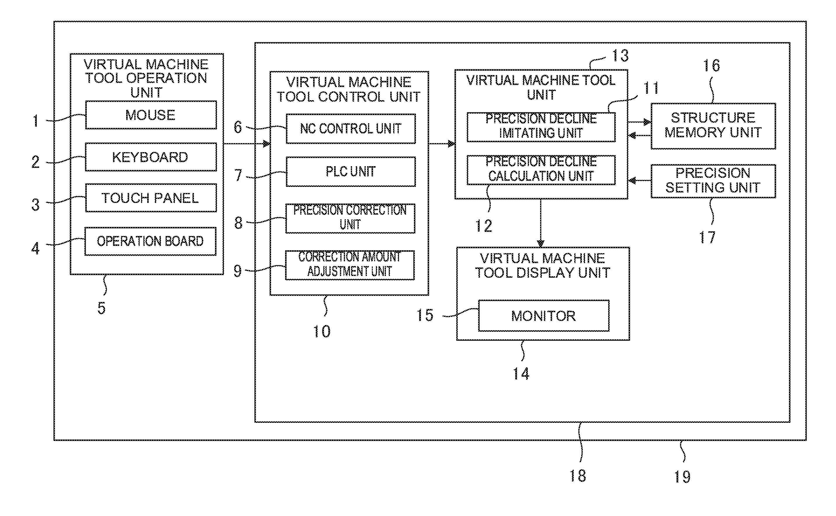
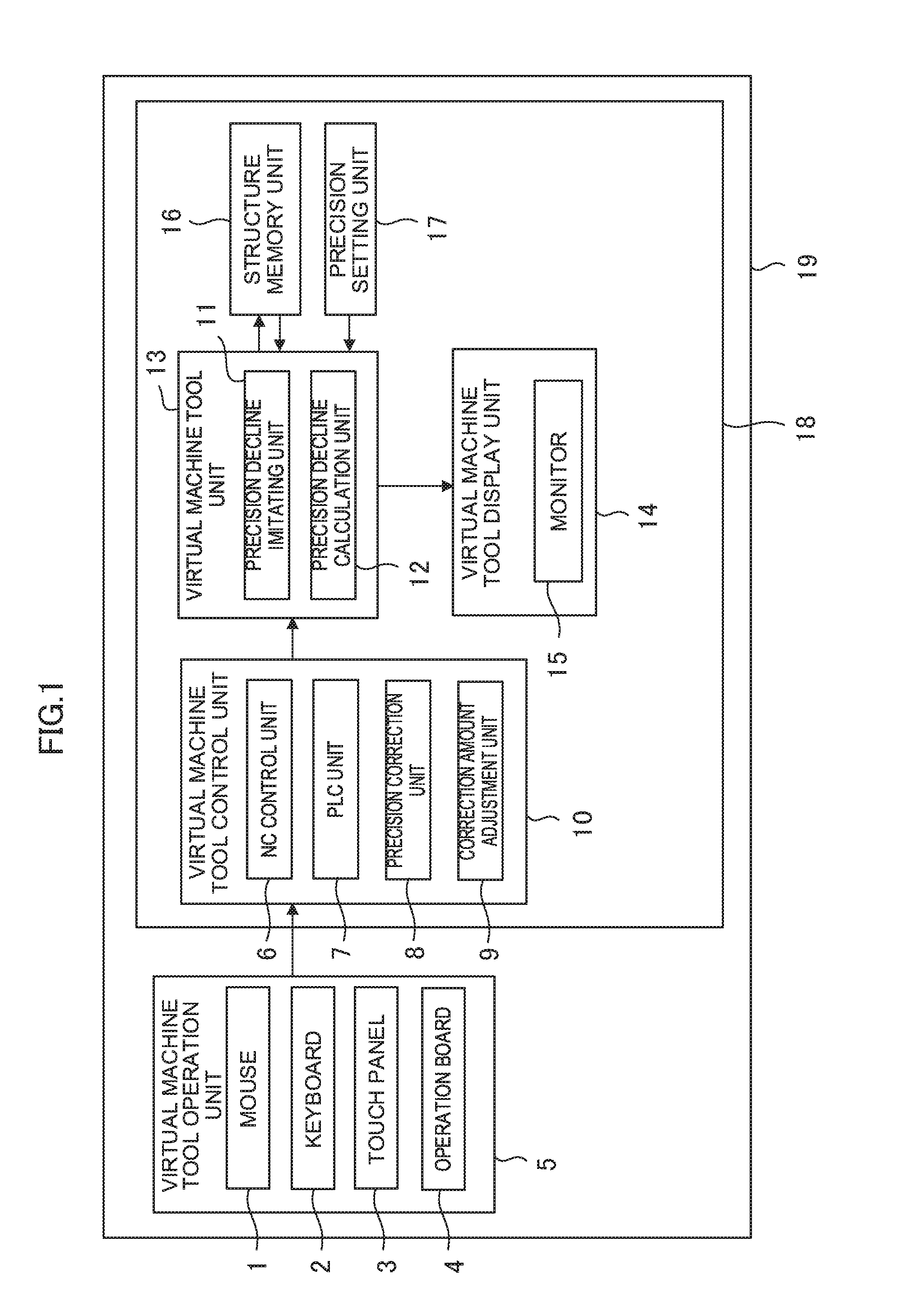
[0021]FIG. 1 is a functional block diagram showing the thermal displacement correction training unit according to the present invention. A thermal displacement correction training unit 19 for the thermal displacement correction without the need for an actual machine tool is prepared. An operator of a machine tool can learn the method for thermal displacement correction and the adjustment method for thermal displacement using the thermal displacement correction training unit 19.

[0022]The thermal displacement correction training unit 19 is provided on a computer 18 with a virtual machine tool control unit 10, a virtual machine tool unit 13 and a virtual machine tool display unit 14.

[0023]In order to train an operator for a machine tool, the virtual machine tool unit 13 in the thermal displacement correction training unit 19 calculates a virtual model of a machine tool so as to display the calc...


PUM


Abstract

A thermal displacement correction training unit has a virtual machine tool, a virtual machine tool control unit and a virtual machine tool display unit. The virtual machine tool has a precision decline imitating unit for imitating the process precision decline caused by the heat during operation in the virtual machine tool unit, and a precision decline calculation unit for finding the amount of precision decline that represents the process precision decline in the process machine unit imitated by the process precision imitating unit. The virtual machine tool control unit has a precision correction unit for finding the correction amount by which the processing point is corrected in response to thermal displacement, and a correction amount adjustment unit for adjusting the correction amount found by the precision correction unit. The virtual machine tool display unit displays the amount of precision decline and the correction amount.

Description

BACKGROUND OF THE INVENTION[0001]1. Field of the Invention[0002]The present invention relates to a thermal displacement correction training unit for simulating on a computer a precision correction method and an adjustment method for a machine tool.[0003]2. Description of the Related Art[0004]When a work is processed using a machine tool, a microscopic displacement (hereinafter referred to as thermal displacement) is generated in the structure of the machine tool due to heat generated from the motor and the ball screws that form the machine tool and the processed portion of the work, cooling by the cooling oil or the cooling air, and disturbance by the outside air temperature. As a result, the point at which the work is processed slips, which becomes one of the major factors that affect the process precision. As a countermeasure for such thermal displacement, there is a method for correcting the slippage of the processing point by predicting the amount of heat generated at the time o...

Claims


Application Information

Patent Timeline
Patent Type & Authority Applications(United States)
IPC IPC(8): G05B19/404
CPCG05B19/404G05B2219/33286G05B2219/37506G05B2219/34303G05B2219/49219
Inventor TAKENO, SHOUHEI
Owner FANUC LTD
Why Eureka
Try Eureka