Top guide fitting for a sliding door

a technology for sliding doors and top guides, which is applied in the direction of door/window fittings, wing accessories, wing arrangements, etc., can solve the problems of sliding door impact noise or jerky motion, and achieve the effect of improving the safety of passengers

Inactive Publication Date: 2016-11-24
ZIMMER GUENTHER +1
View PDF6 Cites 1 Cited by
  • Summary
  • Abstract
  • Description
  • Claims
  • Application Information

AI Technical Summary

Benefits of technology

[0004]The door fitting according to the invention comprises a housing in an upper door fitting of a sliding door which comprises a housing and two transverse guide rollers which each are rotatably supported each on a shaft stub, both shaft stubs extend parallel to each other and are arranged symmetrically with respect to a vertical longitudinal center plane. Both shaft stubs are rigidly mounted in the housing. In addition, the transverse guide rollers delimit an intake opening of the housing for guiding the sliding door so as to prevent impact noises and jerky movements of the sliding door.

Problems solved by technology

If there is some play however between the door fitting and a door guide track impact noises or jerky motions of the sliding door may occur.

Method used


Image

  • Top guide fitting for a sliding door
  • Top guide fitting for a sliding door
  • Top guide fitting for a sliding door

Examples


Embodiment Construction

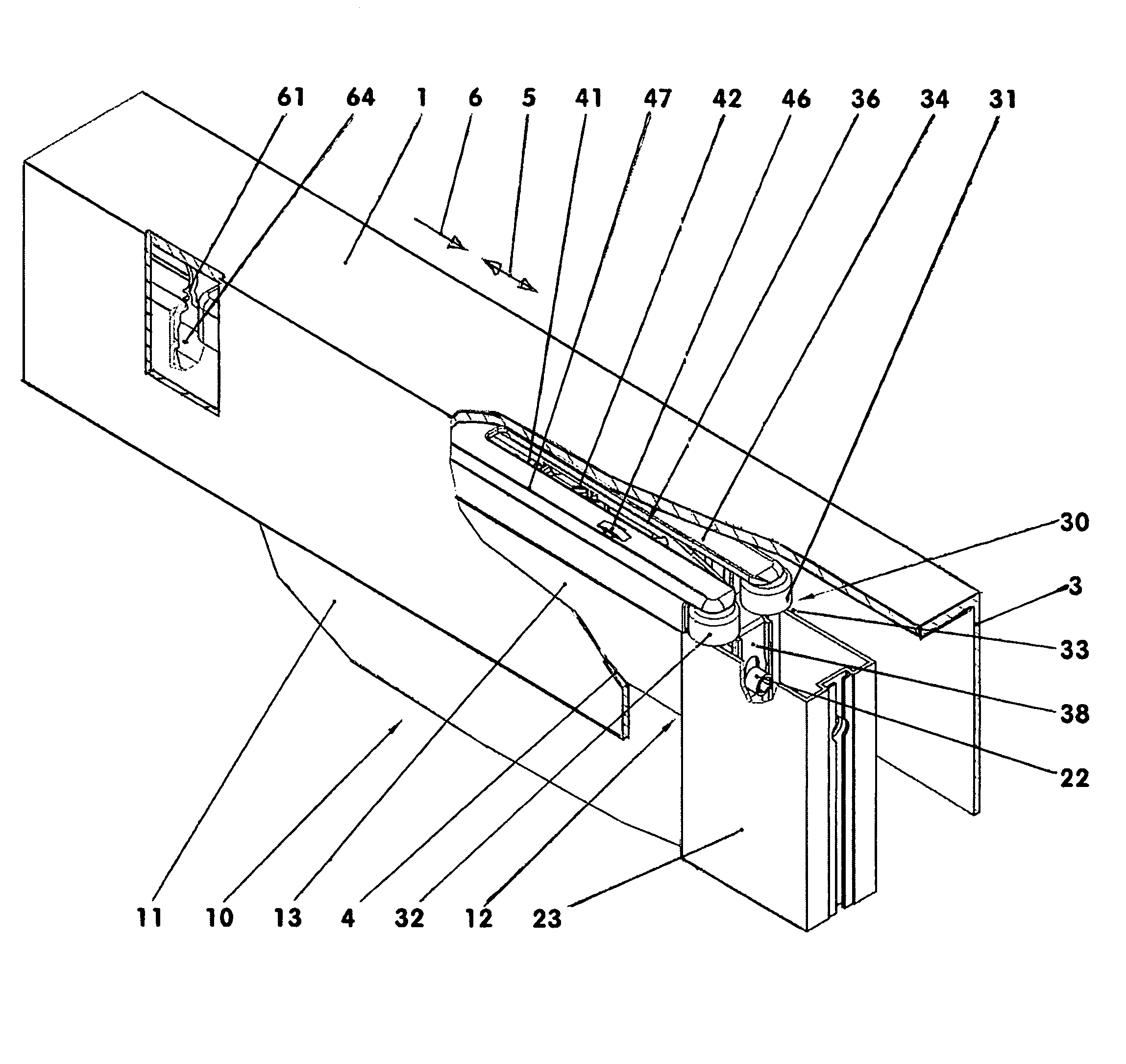
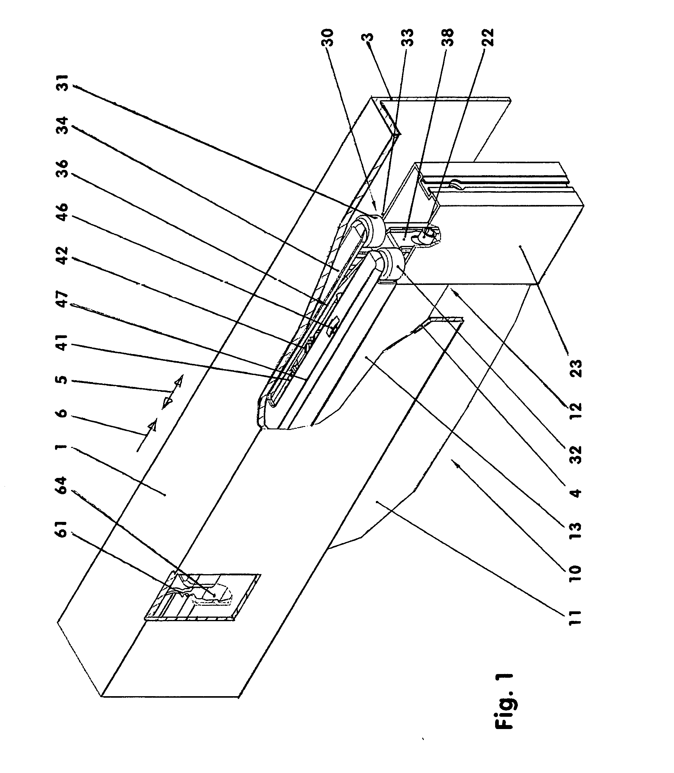
[0012]FIGS. 1 and 2 show the top guide structure of a sliding door 10. The sliding door 10 is accommodated in a U-shaped door guide track 1. Along this door guide track 1, the sliding door 16 is movable between an open and a closed position. The sliding door can be operated manually or by a motor drive.

[0013]The sliding door 10 comprises a multi-part support frame 12 with a sliding door panel 11 disposed therein. On the support frame 12, a door fitting 30 is arranged which, in the longitudinal direction 5, is fixed to the support frame 12 at its two ends. By means of the door fitting 30, the sliding door 10 is guided in the door guide track 1. For the guidance of the sliding door 10, a second door fitting 30 of for example identical design may be arranged at, in longitudinal direction 5, the oppositely oriented end of the sliding door 10. At the bottom end of the sliding door for example support rollers may be arranged.

[0014]In the exemplary embodiment, the support frame 12 comprise...


PUM


Abstract

In an upper door fitting of a sliding door which comprises a housing and two transverse guide rollers which each are rotatably supported each on a shaft stub, both shaft stubs extend parallel to each other and are arranged symmetrically with respect to a vertical longitudinal center plane. Both shaft stubs are rigidly mounted in the housing. In addition, the transverse guide rollers delimit an intake opening of the housing for guiding the sliding door so as to prevent impact noises and jerky movements of the sliding door.

Description

BACKGROUND OF THE INVENTION[0001]The invention concerns a top door fitting of a sliding door, door fitting comprises a housing and two transverse guide rollers each of which is rotatably supported on a shaft stub wherein both shaft stubs extend parallel to one another and are arranged symmetrically with respect to a vertical longitudinal center plane of the door fitting.[0002]CN 203 145 671 V discloses such door fittings. If there is some play however between the door fitting and a door guide track impact noises or jerky motions of the sliding door may occur.[0003]It is the object of the present invention to develop a door fitting which prevents impact noises and jerky motions of the sliding door.SUMMARY OF THE INVENTION[0004]The door fitting according to the invention comprises a housing in an upper door fitting of a sliding door which comprises a housing and two transverse guide rollers which each are rotatably supported each on a shaft stub, both shaft stubs extend parallel to ea...

Claims


Application Information

Patent Timeline
Patent Type & Authority Applications(United States)
IPC IPC(8): E05D15/06E06B3/46
CPCE06B3/4636E05D15/0652E05Y2900/132E05Y2201/21E05Y2201/64E05Y2201/692E05Y2600/46E05D15/063
Inventor ZIMMER, GUENTHERZIMMER, MARTIN
Owner ZIMMER GUENTHER
Why Eureka
Try Eureka