Near-isothermal compressor/expander

a compressor and near-isothermal technology, applied in the direction of positive displacement liquid engine, piston pump, separation process, etc., can solve the problems of small thickness, impracticality of conventional heavy metal heat exchangers, and inability to meet the requirements of small thickness,

Active Publication Date: 2016-11-24
OTHER LAB
View PDF3 Cites 20 Cited by
  • Summary
  • Abstract
  • Description
  • Claims
  • Application Information

AI Technical Summary

Problems solved by technology

Power plants and other implementations are similarly limited by heat exchanger ΔT via the Carnot efficiency
This can be impractical with conventional heavy metallic heat exchangers.
Additionally, conventional metallic heat exchangers become fragile and corrosion sensitive at small thickness.

Method used


Image

  • Near-isothermal compressor/expander
  • Near-isothermal compressor/expander
  • Near-isothermal compressor/expander

Examples


Embodiment Construction

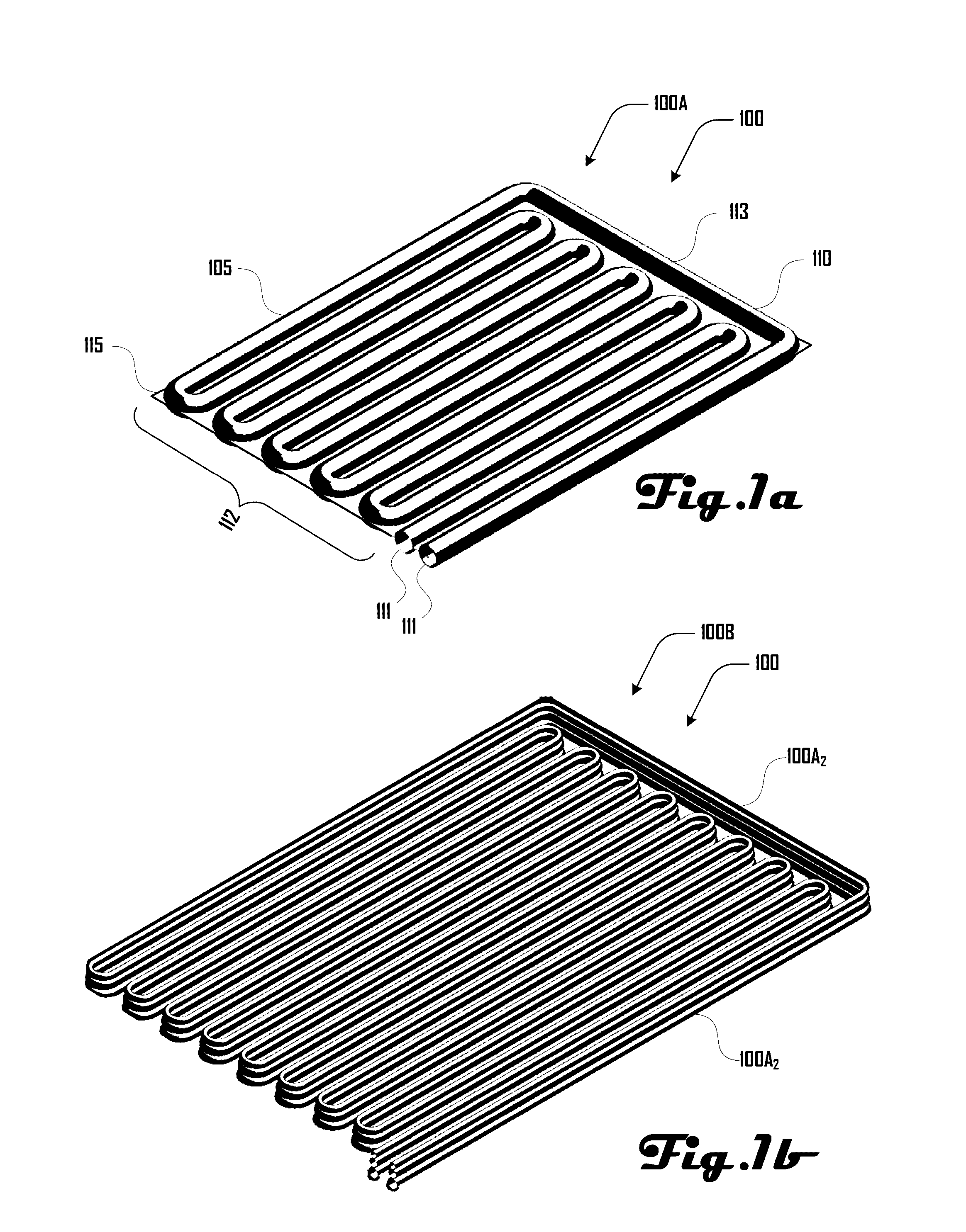
[0042]Turning to FIG. 1a, a first embodiment 100A of a membrane heat exchanger 100 is shown as comprising a body 105 that includes an elongated chamber 110 disposed within a sheet portion 115, with the chamber 110 extending from both sides of the body 105. The chamber 110 includes a pair of ends 111 with a snaking or switchback portion 112 and a wrapping portion 113 that surrounds the switchback portion 112 such that the ends 111 are disposed proximate to each other. FIG. 1b illustrates an alternative configuration 100B wherein a trio of the structures 100A of FIG. 1a are disposed in a stacked arrangement.

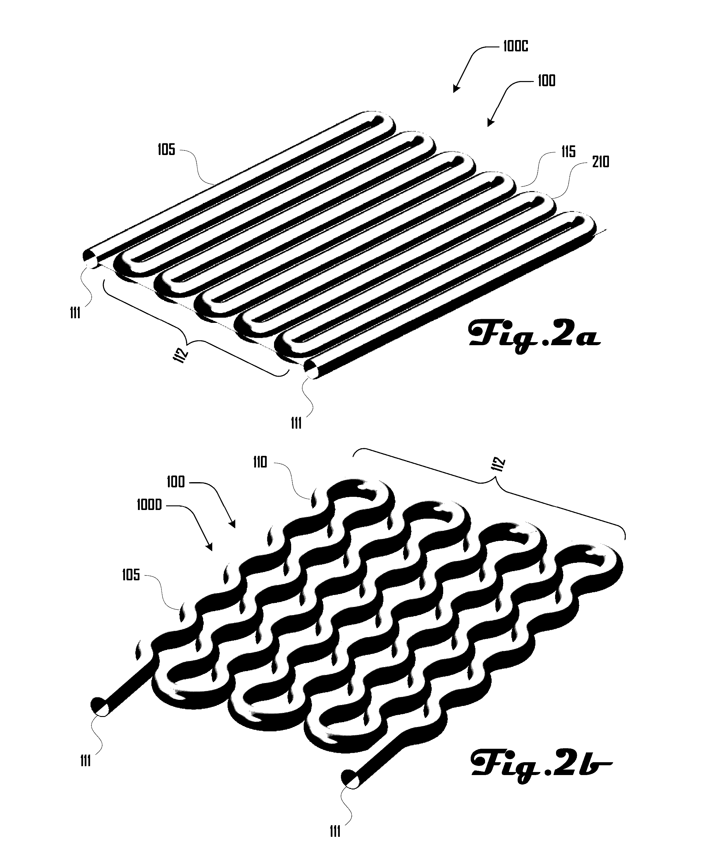
[0043]FIG. 2a illustrates a further embodiment 100C of a membrane heat exchanger 100 that is similar to the embodiment of FIG. 1a, but without the wrapping portion 113. Accordingly, the ends 111 of the chamber 110 are disposed on opposing ends of the switchback portion 112. FIG. 2b illustrates a further example embodiment 110C, wherein the elongated portions of the switchback porti...


PUM

PropertyMeasurementUnit
compressibleaaaaaaaaaa
temperatureaaaaaaaaaa
lengthaaaaaaaaaa

Abstract

One aspect includes an isothermal compressor that includes an isothermal body, an isothermal cavity defined by the isothermal body, a compressible membrane heat exchanger disposed within the isothermal cavity that defines at least one first fluid chamber, and an actuating assembly configured to compress the membrane heat exchanger. A further aspect includes an isothermal engine that includes the isothermal compressor.

Description

CROSS-REFERENCE TO RELATED APPLICATIONS[0001]This application is a non-provisional of and claims priority to U.S. Provisional Application No. 62 / 164,443, filed May 20, 2015, entitled “Membrane Heat Exchanger System and Method” which application is hereby incorporated herein by reference in its entirety and for all purposes. This application is also related to co-pending U.S. application Ser. No. ______ filed May 20, 2016 having attorney docket number 105198-007US0 entitled “Membrane Heat Exchanger System And Method.”BACKGROUND[0002]In various embodiments, the temperature difference ΔT across a heat exchanger directly equates to a loss in exergy. The Carnot coefficients of performance for heat pumps in cooling and heating systems are:COPcooling=Tc-ΔT(Th+ΔT)-(Tc-ΔT)COPheating=Th+ΔT(Th+ΔT)-(Tc-ΔT)(1)[0003]where Th and Tc are hot and cold temperatures at either end of the system and ΔT is the additional temperature difference required to transfer heat to the air through a heat exchanger...

Claims


Application Information

Patent Timeline
Patent Type & Authority Applications(United States)
IPC IPC(8): F15B15/10F04B45/02F04B25/00F04B39/00B01D1/28F04B53/14C02F1/04C02F1/06B01D1/26F04D25/08F04B39/12
CPCF15B15/10F04D25/088F04B45/02F04B25/005F04B39/0094C02F2103/08F04B53/144C02F1/041C02F1/06B01D1/26B01D1/289F04B39/12F28F3/06F28F3/14F28F21/065F28B1/06F28D1/0472F28D7/005B01D1/02F04B35/01F28F21/062F28D1/024F28D1/0477B01D1/28F28D2021/0063
Inventor LYNN, PETERGRIFFITH, SAULROMANIN, VINCENT DOMENIC
Owner OTHER LAB
Why Eureka
Try Eureka