Liquid crystal display

a liquid crystal display and display technology, applied in non-linear optics, instruments, optics, etc., can solve the problems of undesirable etching rate reduction, and achieve the effect of preventing a drop in the aperture ratio

Active Publication Date: 2016-11-24
STANLEY ELECTRIC CO LTD
View PDF15 Cites 0 Cited by
  • Summary
  • Abstract
  • Description
  • Claims
  • Application Information

AI Technical Summary

Benefits of technology

[0007]One object of a specific mode of the present invention is to provide a technique capable of preventing, while ensuring display uniformity in a liquid crystal display provided with a plurality of openings, a disconnection between the openings and additionally preventing a drop in aperture ratio.
[0009]According to the configuration described above, it is possible to prevent, while ensuring display uniformity in the liquid crystal display provided with the plurality of openings, a disconnection between the openings and additionally preventing a drop in aperture ratio.

Problems solved by technology

Due to this kind of variation in the etching precision, there is a drawback in that the slits become joined with each other in their respective longitudinal directions, and a partial disconnection occurs in an electrode.
Nevertheless, lowering etching rate is undesirable since the production efficiency of the liquid crystal display will drop when the etching rate is lowered.
Nonetheless, since the effective aperture ratio of a display unit of the liquid crystal display will drop as the slit width is enlarged, this measure is undesirable.

Method used


Image

  • Liquid crystal display
  • Liquid crystal display
  • Liquid crystal display

Examples


example 1

Constructional Example 1

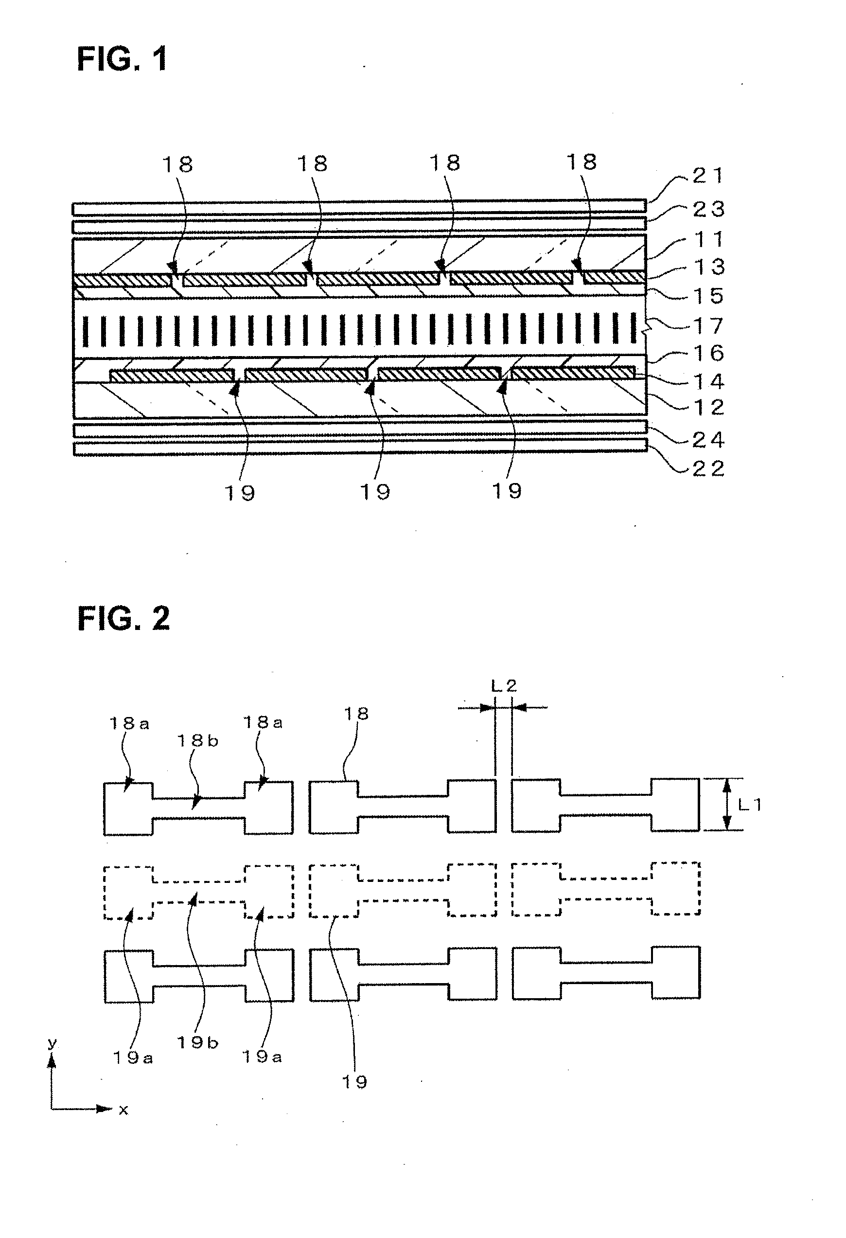
[0054]FIG. 2 is a plan view of the first openings and the second openings of a constructional example 1. The respective first openings 18 and second openings 19 are disposed such that their respective longitudinal directions are along the illustrated x direction (first direction), and their respective short directions are along the illustrated y direction (second direction). The respective first openings 18 and second openings 19 are arranged with regularity by forming a column in the x direction, and forming a row in the y direction. Moreover, the respective first openings 18 and second openings 19 are disposed one after the other (alternately) along the y direction.

[0055]Each first opening 18 has portions 18a having a relatively large slit width (length in the short direction) at respective one end side and another end side, along the longitudinal direction, and a portion 18b having a relatively small slit width between the two portions 18a. Each of these p...

example 2

Constructional Example 2

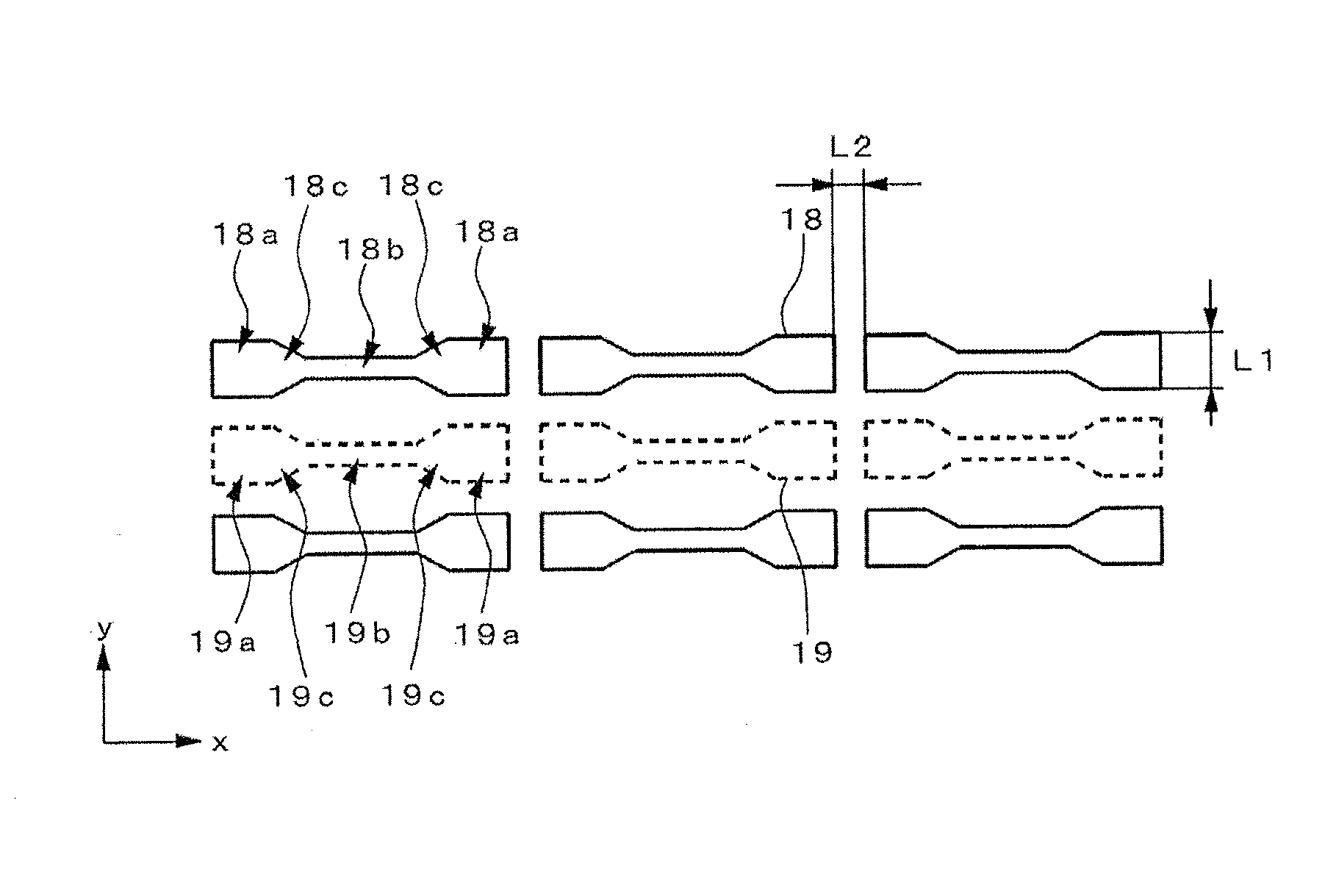
[0058]FIG. 4 is a plan view of the first openings and the second openings of a constructional example 2. The respective first openings 18 and second openings 19 are disposed such that their respective longitudinal directions are along the illustrated x direction, and their respective short directions are along the illustrated y direction. The respective first openings 18 and second openings 19 are arranged with regularity by forming a column in the x direction, and forming a row in the y direction. Moreover, the respective first openings 18 and second openings 19 are disposed one after the other (alternately) along the y direction.

[0059]Each first opening 18 has portions 18a having a relatively large slit width at respective one end side and another end side, along the longitudinal direction, a portion 18b having a relatively small slit width between the two portions 18a, and slope-shaped portions 18c which are disposed between and connects each portion 18a a...

example 3

Constructional Example 3

[0063]FIG. 7 is a plan view of the first openings and the second openings of a constructional example 3. The respective first openings 18 and second openings 19 are disposed such that their respective longitudinal directions are along the illustrated x direction, and their respective short directions are along the illustrated y direction. The respective first openings 18 and second openings 19 are arranged with regularity by forming a column in the x direction, and forming a row in the y direction. Moreover, the respective first openings 18 and second openings 19 are disposed one after the other (alternately) along the y direction.

[0064]Each first opening 18 has portions 18a having a relatively large slit width at respective one end side and another end side, along the longitudinal direction, a portion 18b having a relatively small slit width between the two portions 18a, and slope-shaped portions 18c which are disposed between and connects each portion 18a a...


PUM

PropertyMeasurementUnit
angleaaaaaaaaaa
angleaaaaaaaaaa
thicknessaaaaaaaaaa

Abstract

A liquid crystal display includes first and second substrates; first and second electrodes provided on the first and second substrates respectively; and a liquid crystal layer provided between the first and second substrates. The first electrode includes first openings each having an elongated shape in a first direction and which are arranged with regularity, and a short side edge thereof is longer than a length between the first openings adjacent in the first direction. The second electrode includes second openings each having an elongated shape in the first direction and which are arranged with regularity, and a short side edge thereof is longer than a length between the second openings adjacent in the first direction. Each of the first and second openings has a recess in at least either of two outer edge parts along the first direction in a planar view.

Description

CROSS-REFERENCE OF RELATED APPLICATIONS[0001]This application is a Continuation of copending application Ser. No. 13 / 920,720, filed on Jun. 18, 2013, which claims priority under 35 U.S.C. §119(a) to Application No. 2012-139204, filed in Japan on Jun. 20, 2012, all of which are hereby expressly incorporated by reference into the present application.BACKGROUND OF THE INVENTION[0002]1. Field of the Invention[0003]The present invention relates to a liquid crystal display having a plurality of openings (slits) in an electrode.[0004]2. Description of the Related Art[0005]Japanese Patent No. 4107978 (Patent Document 1) discloses a liquid crystal display in which an opening (slit) is provided to each of transparent electrodes placed opposite each other across a liquid crystal layer. With this liquid crystal display, a fringe electric field is generated in two different directions based on the effect of the slits and applied to the liquid crystal layer, whereby a two-domain alignment structu...

Claims


Application Information

Patent Timeline
Patent Type & Authority Applications(United States)
IPC IPC(8): G02F1/1343G02F1/1335G02F1/1337
CPCG02F1/13439G02F1/1337G02F1/133528G02F2001/133746G02F2001/133742G02F2001/133765G02F1/134336G02F1/133742G02F1/133746G02F1/133765
Inventor IWAMOTO, YOSHIHISA
Owner STANLEY ELECTRIC CO LTD
Why Eureka
Try Eureka