Device with integral insert having strap slot

a technology of inserts and slots, which is applied in the field of devices with integral inserts having strap slots, can solve the problems of the strap, and reducing the frictional force of the device. , to achieve the effect of increasing the frictional force, reducing or adjusting the friction created between the device and the strap

Inactive Publication Date: 2016-12-01
LIMBALIGN
View PDF0 Cites 0 Cited by
  • Summary
  • Abstract
  • Description
  • Claims
  • Application Information

AI Technical Summary

Benefits of technology

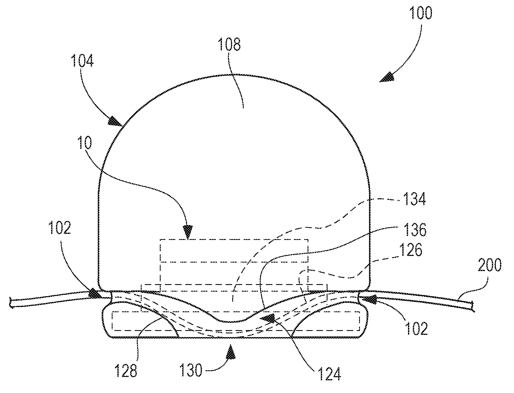
[0009]The device can include several different shapes or structures in order to increase, decrease or otherwise adjust the friction created between the device and the strap. According to one embodiment, the bottom end of the device, adjacent to the slot, can include two openings spaced apart by a weaving section or cross-bar. In such an embodiment, the strap can be inserted into the device slot, out one of the openings, around the weaving section, into the other opening and then continue through the device slot before exiting the device. According to another embodiment, the device bottom end can include a bulge region projecting from the upper end of the slot inside the device. In such an embodiment, the strap is forced to conform to the bulging region inside the slot which can increase the frictional forces between the strap and the device. In yet another embodiment, the bottom end of the device can include an angled bulge region projecting from the upper end of the slot inside the device. The angled bulge can have angled (as opposed to rounded) edges. The bottom end of the device can also have an opening defined therein with sides that correspond to the edges of the angled bulge in order to create narrowed gaps through which the strap passes. In such an embodiment, the strap is inserted into the slot of the device, around the angled edges of the bulge and through the narrowed gaps and then out the other end of the device. Sharper angles and narrowed gaps can increase the frictional resistance of the strap and the device.

Problems solved by technology

However, devices constructed of materials, such as foam or rubber for example, often lack the structural characteristics, such as durability and strength, necessary for withstanding the forces that may be generated by the strap or restraining mechanism.
To this end, when a force is exerted on an object, the site at which the device engages with or receives the strap may be subjected to tearing, failure or undesirable deflection, particularly when that site has a reduced material thickness.
When a significant amount of force is exerted on the device, it is conceivable that portions of the device adjacent the slot having a reduced material thickness could tear or fail, particularly in embodiments where the device is constructed of a foam material.
Other devices configured for use with a strap or similar retaining means similarly face limitations with wear and tear due to the forces and stresses applied to the device by the strap.

Method used


Image

  • Device with integral insert having strap slot
  • Device with integral insert having strap slot
  • Device with integral insert having strap slot

Examples


Embodiment Construction

[0039]The invention will now be described with reference to the drawing figures, in which like reference numerals refer to like parts throughout. For purposes of clarity in illustrating the characteristics of the present invention, proportional relationships of the elements have not necessarily been maintained in the drawing figures. It will be appreciated that terms such as “top,”“bottom,”“upper,”“lower,”“above,”“below,”“left,”“right,”“side,”“end,”“front” and “back,” used herein are merely for ease of description and refer to the orientation of the components as shown in the figures. It should be understood that any orientation of the present invention, and the components thereof described herein, is within the scope of the present invention.

[0040]The following detailed description of the invention references specific embodiments in which the invention can be practiced. The embodiments are intended to describe aspects of the invention in sufficient detail to enable those skilled in...


PUM


Abstract

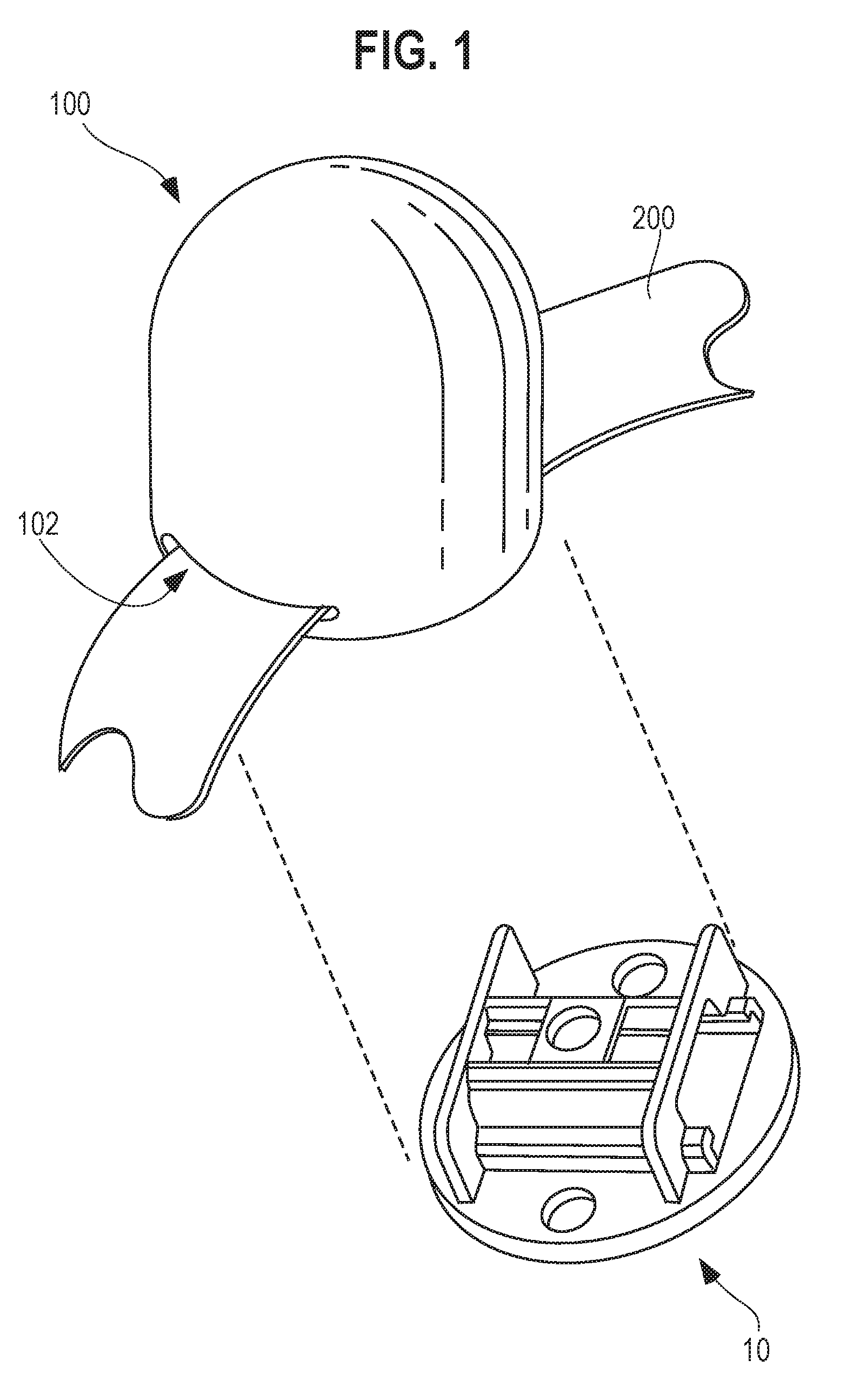
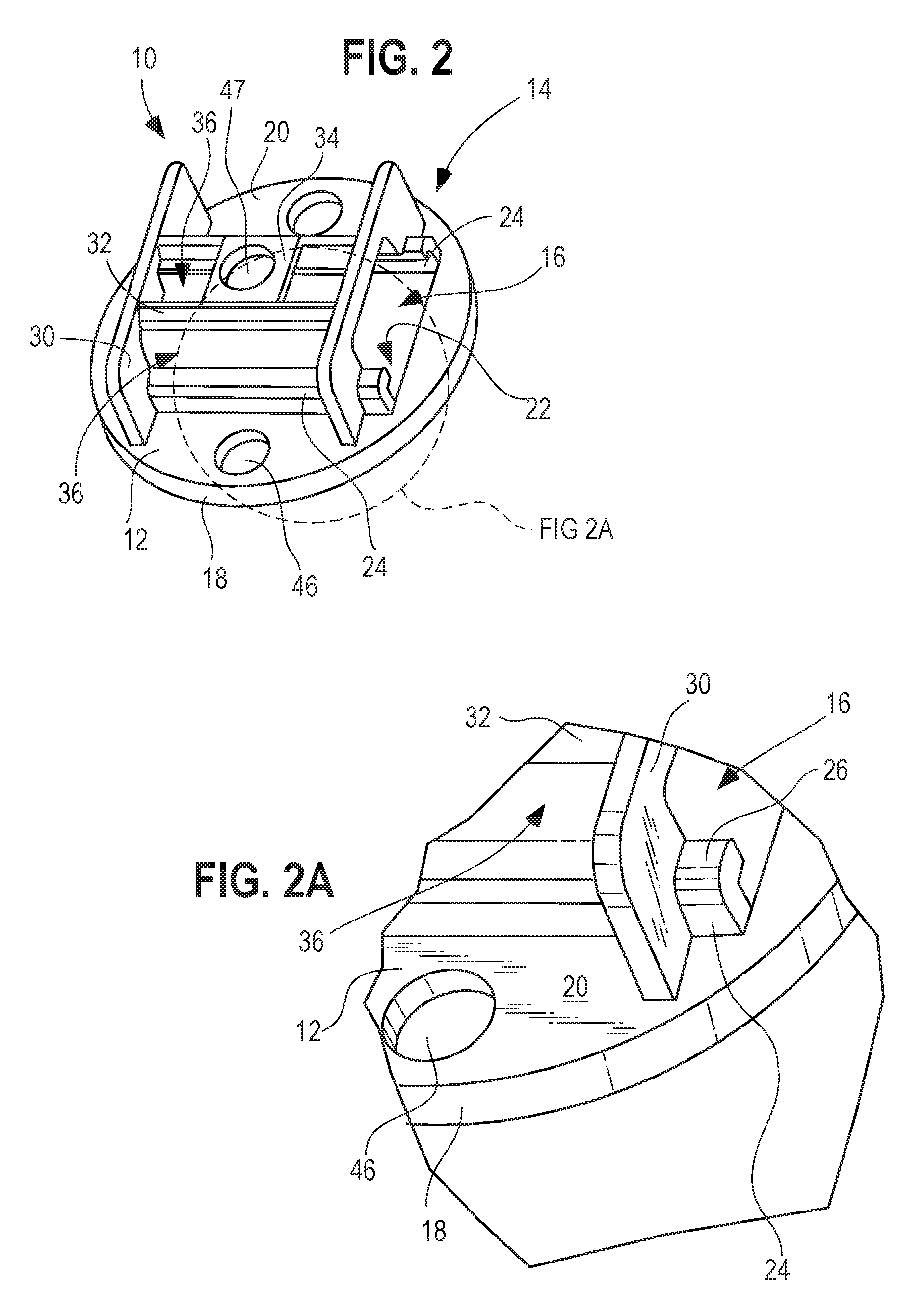
An insert and a device are provided. The device can include a body portion and a slot defined through the body portion. The slot can be configured for receiving a strap that can secure the device in place relative to the strap. The insert can be designed to strengthen the device by being inserted into the device and receiving the strap. The insert can include a main body portion and a projecting body portion. The projecting body portion can include a slot similarly sized to the slot of the device so that when the insert is positioned within the device, the slot of the insert and the slot of the device generally align. The projecting body of the insert can include inward flanges to define part of an upper boundary of the slot and assist in securing the strap within the slot.

Description

CROSS-REFERENCE TO RELATED APPLICATIONS[0001]This Application claims priority to U.S. Provisional Patent Application Ser. No. 62 / 168,035, filed on May 29, 2015, to David B. Tannahill et al., entitled “Device with Integral Insert Having Strap Slot,” currently pending, the entire disclosure of which is incorporated herein by reference.BACKGROUND OF THE INVENTION[0002]It is often desirable to locate, position, and / or hold objects or devices in selectively adjustable positions through the use of straps and the like. Such devices commonly have some type of opening or connecting means through which a strap or similar retention mechanism is inserted in order to retain the device on the strap. However, devices constructed of materials, such as foam or rubber for example, often lack the structural characteristics, such as durability and strength, necessary for withstanding the forces that may be generated by the strap or restraining mechanism. To this end, when a force is exerted on an objec...

Claims


Application Information

Patent Timeline
Patent Type & Authority Applications(United States)
IPC IPC(8): A44B11/10
CPCA44B11/10A44B11/005A44B11/04
Inventor TANNAHILL, DAVID B.GUERRA, LAWRENCE E.
Owner LIMBALIGN
Why Eureka
Try Eureka