Internal combustion engine control system

a control system and combustion engine technology, applied in the direction of electrical control, process and machine control, instruments, etc., can solve the problems of increasing the complexity of engine control strategies, affecting the actual performance of the cylinder, and affecting the operation of the cylinder, so as to reduce the error, reduce the error, and improve the effect of tracking actual cylinder performan

Inactive Publication Date: 2007-04-19
WISCONSIN ALUMNI RES FOUND +1
View PDF19 Cites 28 Cited by
  • Summary
  • Abstract
  • Description
  • Claims
  • Application Information

AI Technical Summary

Benefits of technology

[0014] Since a virtual cylinder model may not perfectly track the behavior of the actual cylinder, particularly if a simpler model is used, actual / measured engine parameters can be used as feedback to the virtual cylinder model to adapt its behavior to better track actual cylinder performance. This can be done, for example, by providing the control system with measurements of the air supplied to all cylinders during each engine cycle (i.e., the actual MAP and / or MAF), comparing these values to the estimated values calculated by the virtual cylinder models, and adapting the virtual cylinder models (or the actual engine) to reduce the error between estimated and actual values. As an example, the virtual cylinder models can be used to calculate an estimated MAF, and if error exists between the actual (measured) MAF and the virtual (estimated) MAF, the virtual cylinder model can be adapted to reduce or eliminate the error—for example, by adapting the virtual cylinder model to increase or decrease the temperature of the air supplied to the virtual cylinder, thereby increasing or decreasing its density, and thus increasing or decreasing the virtual (estimated) MAF. Additionally or alternatively, the virtual cylinder models can be used to calculate an estimated MAP, and if error exists between the actual (measured) MAP and the virtual (estimated) MAP, the throttle area in the virtual cylinder model (or on the actual engine) can be adapted to reduce or eliminate the error.
[0015] Since the virtual cylinder models can track the mass flows out of a cylinder as well as into it, they can also be used to determine and control parameters such as residual exhaust gas (the combustion products retained within the cylinder at the end of the exhaust stroke). Since residual exhaust gas can lower combustion temperature (and thereby reduce NOx emissions), it is a useful parameter to control. Thus, for example, a virtual cylinder model can determine the amount of exhaust gas expelled from a (virtual) cylinder, and thereby know the amount retained when the (virtual) exhaust valve(s) close. This residual exhaust gas can then be considered alongside the air accepted by the (virtual) intake valve(s) during the next engine cycle (i.e. alongside the MAC) when determining the amount of fuel to inject. Since it is generally desirable to advance the spark as residual exhaust gas increases, the control system can then use the estimated residual exhaust gas (as well as the estimated MAC) to set the actual spark timing for the actual cylinder. Additionally or alternatively, the timing and lift of the exhaust valve (and possibly the intake valve) can be adapted by the control system to attain some desired amount of residual exhaust gas.

Problems solved by technology

Older internal combustion engines, having valve opening and closing occurring at the same times during the engine cycle in dependence on engine-driven cams, had the drawback that the fixed valve opening and closing times (as well as the valve lift profiles, i.e., the degree of lift over time) were optimized for a certain speed range.
At this speed range, fuel efficiency, emissions, and power would be optimized, but at other speeds the balance between these factors would vary: for example, an engine designed to have its cams actuate the valves for some preferred fuel efficiency, emissions, and power at high speed might have poor fuel efficiency, emissions, and power at low speed.
However, greater freedom in valve actuation bears greater complexity with engine control strategies.
However, the speed density model has several drawbacks.
Initially, since changes in valve timing and lift also change engine parameters such as volumetric efficiency, it becomes difficult and burdensome to generate look-up tables for all possible valve states.
The end effect is that the MAC calculated from the MAP is less accurate than it ideally could be, particularly during transient engine conditions, and thus dependent events such as fuel injection amounts and timing, spark timing, etc. are nonideal as well.
This in turn results in lost performance, wasted fuel, and / or greater emissions.
Additionally, it is often incorrect to assume that the same amount of air is supplied from the manifold to all cylinders which are simultaneously undergoing intake.
Different cylinders often have different gas dynamics depending on the manifold and intake runner configuration, engine speed, etc., and while the difference between cylinders is often minor, these minor differences lead to significant performance loss, fuel waste, and excess emissions, since cylinders having a MAC which deviates from the average are effectively being mis-operated.
These systems are also susceptible to error during transient conditions, particularly where sudden changes in throttle position occur.
However, the cylinders do not take in all of this air, and thus the MAF sensor's reading leads to an inappropriately large MAC estimate and a correspondingly excessive fuel pulse.
Similarly, when the throttle is suddenly closed, the cylinders can draw more air than the MAF sensor measures, leading to an erroneously low MAC estimate (and insufficient fuel injection).
Thus, MAF-based injection schemes are also imperfect.
However, this is generally not practical owing to cost and space constraints, and the periodic behavior of the gas in the runners (as intake valves open and close) makes it very difficult to practically and economically monitor pressure and / or mass flow in an accurate and reliable manner.

Method used


Image

  • Internal combustion engine control system
  • Internal combustion engine control system

Examples


Embodiment Construction

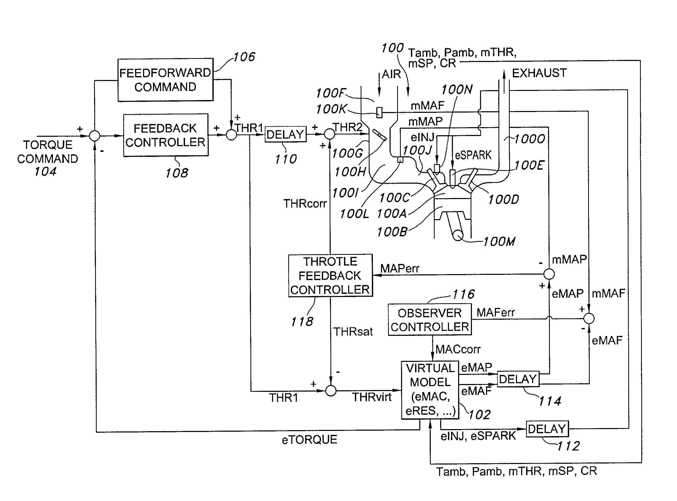
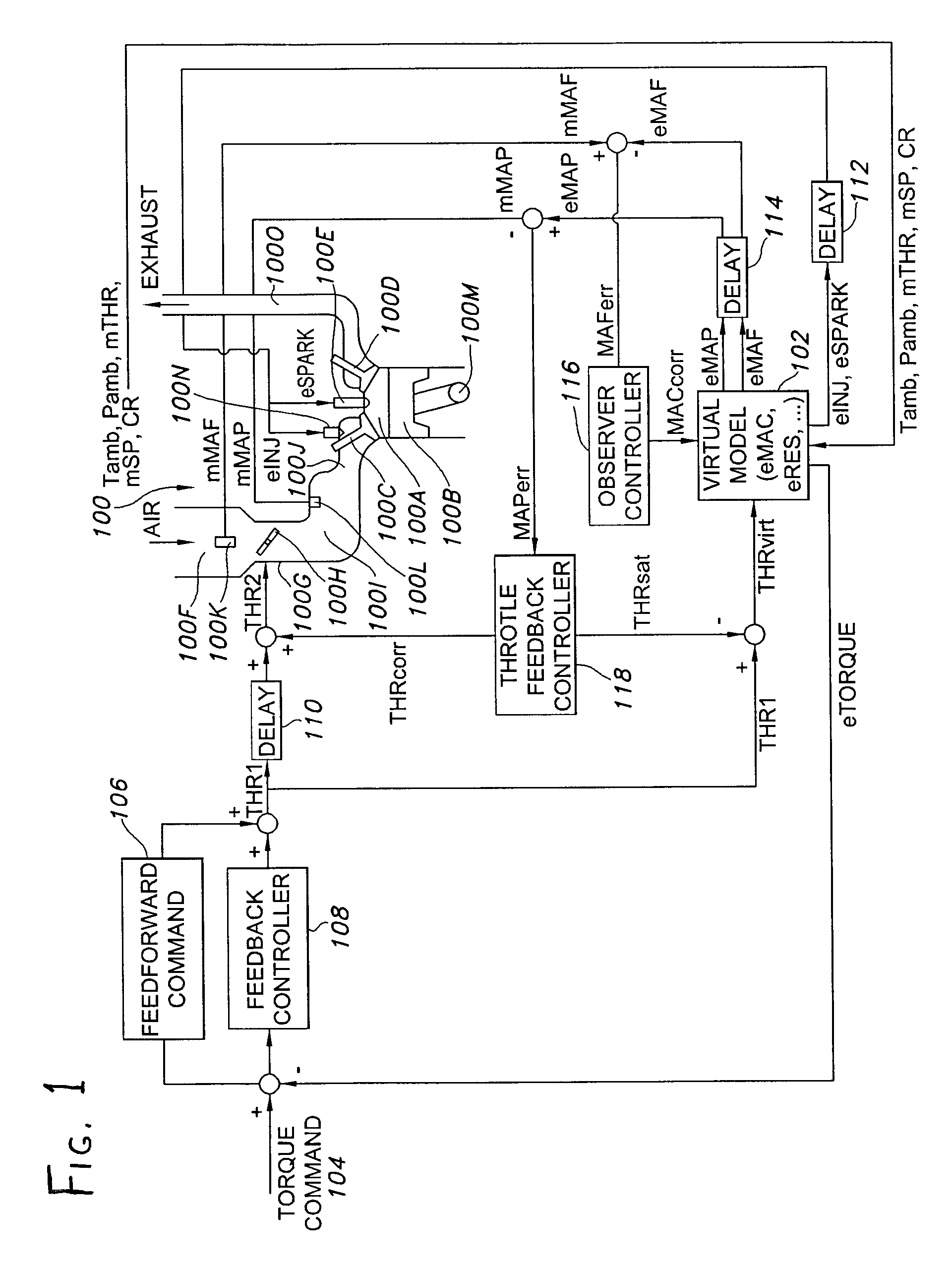
[0018] Referring to FIG. 1 for a depiction of an exemplary version of the invention, an internal combustion engine is depicted at 100. The engine 100 includes a cylinder 100A wherein a piston 100B reciprocates, with an intake valve 100C, exhaust valve 100D, and spark plug 100E being located opposite the piston 100B. Air is supplied to the intake valve 100C via an intake system 100F, which includes a throttle body 100G wherein a throttle 100H is located, an intake manifold 100I, and a runner 100J leading from the manifold 100I to the intake valve 100C. A mass air flow sensor (MAF sensor) 100K is located adjacent the throttle 100H, and a manifold absolute pressure sensor (MAP sensor) 100L is located within the intake manifold 100I. Fuel is supplied to the cylinder 100A over a desired portion of an engine cycle (i.e., over a 720 degree rotation of the crankshaft 100M) by a fuel injector 100N, which is here depicted adjacent the intake valve 100C in a port-style injection arrangement. A...


PUM


Abstract

A control system for an internal combustion engine includes a virtual engine model which mathematically represents the states of the engine in real time, but which is programmed to provide the engine's states at least a fraction of an engine cycle (and preferably at least one-fourth of an engine cycle, i.e., one stroke) to several engine cycles in advance of the real engine. The mass flow entering and leaving the cylinder is modeled, allowing parameters such as the mass of air per cylinder (MAC) and residual exhaust gas to be computed, and thereafter used to generate engine control commands related to fuel injection (air/fuel ratio), spark advance, and so forth.

Description

CROSS-REFERENCE TO RELATED APPLICATIONS [0001] This application claims priority under 35 USC §119(e) to U.S. Provisional Patent Application 60 / 667,384 filed 1 Apr. 2005, the entirety of which is incorporated by reference herein.FIELD OF THE INVENTION [0002] This document concerns an invention relating generally to engine control systems, and more specifically to engine control systems which adjust fuel injection, spark timing, and / or residual exhaust gas to attain desired performance, fuel economy, and emissions. BACKGROUND OF THE INVENTION [0003] Older internal combustion engines, having valve opening and closing occurring at the same times during the engine cycle in dependence on engine-driven cams, had the drawback that the fixed valve opening and closing times (as well as the valve lift profiles, i.e., the degree of lift over time) were optimized for a certain speed range. At this speed range, fuel efficiency, emissions, and power would be optimized, but at other speeds the bala...

Claims


Application Information

Patent Timeline
Patent Type & Authority Applications(United States)
IPC IPC(8): G06F17/00F02M25/07
CPCF02D37/02F02D41/0002F02D41/0062F02D41/008F02D41/1401F02D2041/141F02D2041/1418F02D2041/1433F02D2041/1437F02D2200/0402F02D2200/0408F02D2200/1004F02D2250/12F02D2250/18F02P5/1512Y02T10/46Y02T10/42Y02T10/47Y02T10/40
Inventor LAHTI, JOHN L.MOSKWA, JOHN J.
Owner WISCONSIN ALUMNI RES FOUND
Why Eureka
Try Eureka