Internal combustion engine cooling system

a technology for internal combustion engines and cooling systems, which is applied in the direction of engine cooling apparatus, machines/engines, mechanical equipment, etc., can solve the problems of high production cost and complicated control system, and achieve the effect of low cost and simple structur

Inactive Publication Date: 2008-05-13
TOYOTA JIDOSHA KK
View PDF7 Cites 30 Cited by
  • Summary
  • Abstract
  • Description
  • Claims
  • Application Information

AI Technical Summary

Benefits of technology

[0016]It is an object of the invention to provide an internal combustion engine cooling system having a simple and low-cost structure that enables the internal combustion engine to be preheated before engine start.
[0019]As described above, according to the first aspect of the invention, the collection of the coolant (warm coolant) in the thermal storage device and the preheating before the start of the internal combustion engine may be performed by the valve device that operates in response to the temperature of the coolant, without performing an electrical valve switching control. As such, engine preheating can be performed at a lower cost than the case where a three-way valve is used.
[0020]As one example of the valve device, a check valve that includes a temperature-sensing portion and serves also as a thermostat and may be employed. The check valve loosens the restriction on the flow of the coolant in response to an increase in temperature of the coolant.
[0021]To effectively transmit an increase and a decrease in temperature of the coolant to the temperature-sensing portion provided in the valve device that serves as a thermostat when the coolant flow is restricted by the valve device, the temperature-sensing portion of the valve device may be placed in contact with the coolant from the internal combustion engine, by allowing a leak of the coolant in the valve device and thereby generating a flow of the coolant in the valve device. Alternatively, to place the temperature-sensing portion in contact with the coolant from the internal combustion engine, a pipe may be provided that communicates with a flow passage in which the temperature-sensing portion is arranged, so that the coolant flows through the pipe during the restriction on the flow.
[0022]The temperature-sensing portion of the valve device may be placed in direct contact with the coolant flowing in the internal combustion engine, by disposing the valve device to be in contact with a main body (for example, the cylinder block, or the cylinder head) of the internal combustion engine. With this arrangement, because the valve device is attached to the main body of the internal combustion engine, heat is directly transmitted to the temperature-sensing portion from the main body of the internal combustion engine. That is, the temperature-sensing portion can more efficiently detect an increase and a decrease in the temperature of the coolant, without providing an additional path of the coolant leading to the temperature-sensing portion of the valve device. In addition, the structure for installing the valve device is simplified. It is to be noted that the valve device may be either incorporated in the main body of the internal combustion engine, or disposed outside thereof, as long as the valve device is in contact with the main body of the internal combustion engine.
[0024]According to the invention, the valve device that controls the flow of the coolant in response to the temperature of the coolant is provided between the internal combustion engine and the thermal storage device that stores a portion of the coolant circulating in the internal combustion engine. By the operation of the valve device, the collection of the coolant (warm coolant) in the thermal storage tank and the preheating before the start of the engine can be performed. Thus, engine preheating can be achieved with a simple structure and at a low cost, without using a three-way valve and performing electrical valve switching control.

Problems solved by technology

Further, in the case of a system as shown in FIG. 8 in which a three-way valve is used, a positioning sensor such as a potentiometer needs to be provided along with the three-way valve, therefore the production cost is high.
Also, in a cooling system including a three-way valve, it is necessary to control the switching of the three-way valve based on particular conditions of the engine operation such as the engine being not operating (before engine start), the engine being presently warmed up, and the warming-up of the engine having been completed, which requires a complicated control system.

Method used


Image

  • Internal combustion engine cooling system
  • Internal combustion engine cooling system
  • Internal combustion engine cooling system

Examples


Embodiment Construction

[0033]Hereinafter, exemplary embodiments of the invention will be described with reference to the accompanying drawings.

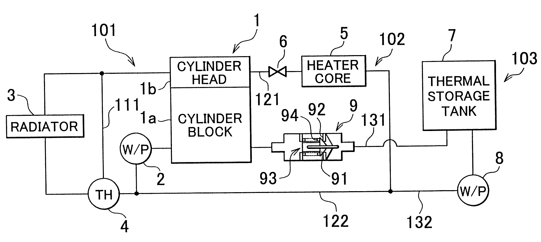
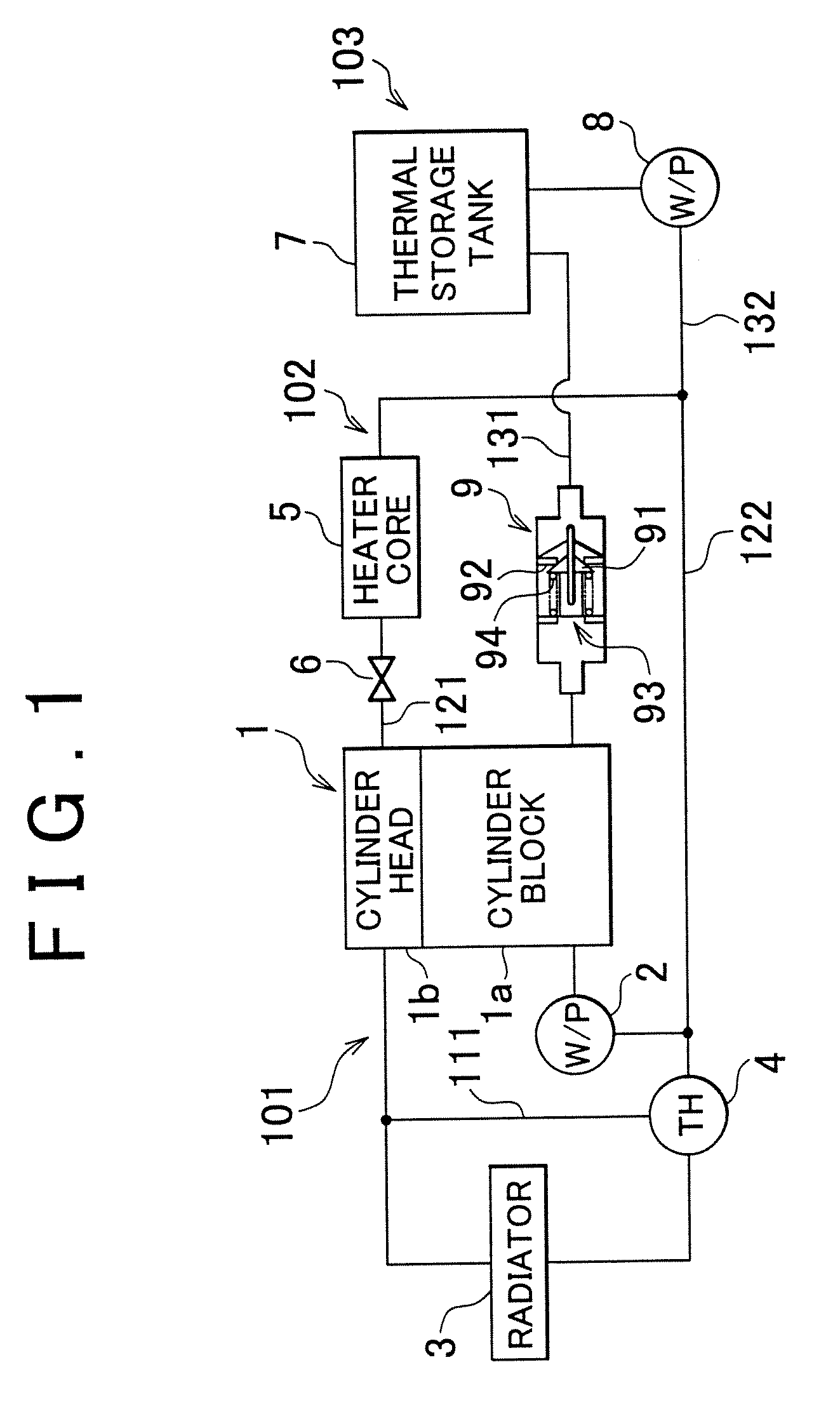
[0034]FIG. 1 shows a circuit diagram of an exemplary embodiment of the cooling system according to the invention.

[0035]The cooling system of this embodiment includes a cooling circuit 101, a heater circuit 102, and a thermal storage circuit 103. The cooling circuit 101 cools a cylinder block 1a and a cylinder head 1b of an engine 1 using coolant. The heater circuit 102 heats a passenger compartment using warm coolant (warm coolant). The thermal storage circuit 103 stores a part of the coolant (warm coolant) in a thermal storage tank 7 while keeping it warm.

[0036]The cooling circuit 101 is provided with a mechanical water pump (W / P) 2, a radiator 3, a thermostat 4, etc. The mechanical water pump (W / P) 2 is driven by the engine 1 to circulate the coolant in the cooling circuit 101. The radiator 3 cools the coolant. The thermostat 4 adjusts the flow rate of the coolan...


PUM


Abstract

A check valve having a thermostat function is provided between an engine and a thermal storage tank that stores a portion of the coolant circulating in the engine. The check valve restricts the flow of the coolant from the engine to the thermal storage tank, and loosens the restriction when the temperature of the coolant increases. Through such operation of the check valve, the warm coolant is collected in the thermal storage tank and engine preheating may be performed before engine start. Thus, by providing between the engine and the thermal storage tank the check valve that operates in response to the temperature of the coolant, engine preheating can be accomplished with a simple structure and at a low cost, without using a three-way valve and performing an electrical valve switching control.

Description

INCORPORATION BY REFERENCE[0001]The disclosure of Japanese Patent Application No. 2005-366022 filed on Dec. 20, 2005 including the specification, drawings and abstract is incorporated herein by reference in its entirety.BACKGROUND OF THE INVENTION[0002]1. Field of the Invention[0003]The invention relates to an internal combustion engine cooling system of.[0004]2. Description of the Related Art[0005]In an internal combustion engine (hereinafter, also referred to as an engine) installed in a vehicle or the like, it is important to warm up the engine as quickly as possible after the engine is started to improve fuel economy and reduce exhaust emissions.[0006]Conventionally, to quickly warm-up a water-cooled engine, a cooling system stores part of the coolant that has been warmed during the operation of an internal combustion engine and keeps the stored coolant warm. The warm coolant may be stored in a thermal storage tank and used to preheat (pre-warm) the engine before the next engine...

Claims


Application Information

Patent Timeline
Patent Type & Authority Patents(United States)
IPC IPC(8): F01P11/02F01P7/16
CPCF01P11/20F01P2007/146F01P2011/205
Inventor HANAI, SHUICHI
Owner TOYOTA JIDOSHA KK
Why Eureka
Try Eureka