Horizontal boring machine tool

a horizontal boring machine and tool technology, applied in the field of horizontal boring machines, can solve the problems of unthinkable arrangement of multiple cutting bits axially spaced apart from each other on the boring bar, inability to make an automatic radial adjustment system for all the cutting bits carried by the boring bar, and inability to make a radial adjustment system in practice. , to achieve the effect of reducing the machining cycle time and simple and low-cost structur

Inactive Publication Date: 2007-03-27
COMAU SPA
View PDF16 Cites 7 Cited by
  • Summary
  • Abstract
  • Description
  • Claims
  • Application Information

AI Technical Summary

Benefits of technology

[0008]The object of this invention is that of providing a machine of the type indicated at the beginning that is capable of reducing the machining cycle time for a number of cylindrical seats axially spaced apart from each other and, nevertheless, always permits radial adjustment of the cutting bit to be automatically performed, and which still has a relatively simple and low-cost structure.

Problems solved by technology

The main drawback of the above-described machine is that it necessitates machining the seats one at a time, which implies a relatively high cycle time.
On the other hand, an arrangement with multiple cutting bits axially spaced apart from each other on the boring bar is unthinkable, as in this case it would be impossible in practice to make an automatic radial adjustment system for all of the cutting bits carried by the boring bar.

Method used


Image

  • Horizontal boring machine tool
  • Horizontal boring machine tool
  • Horizontal boring machine tool

Examples


Embodiment Construction

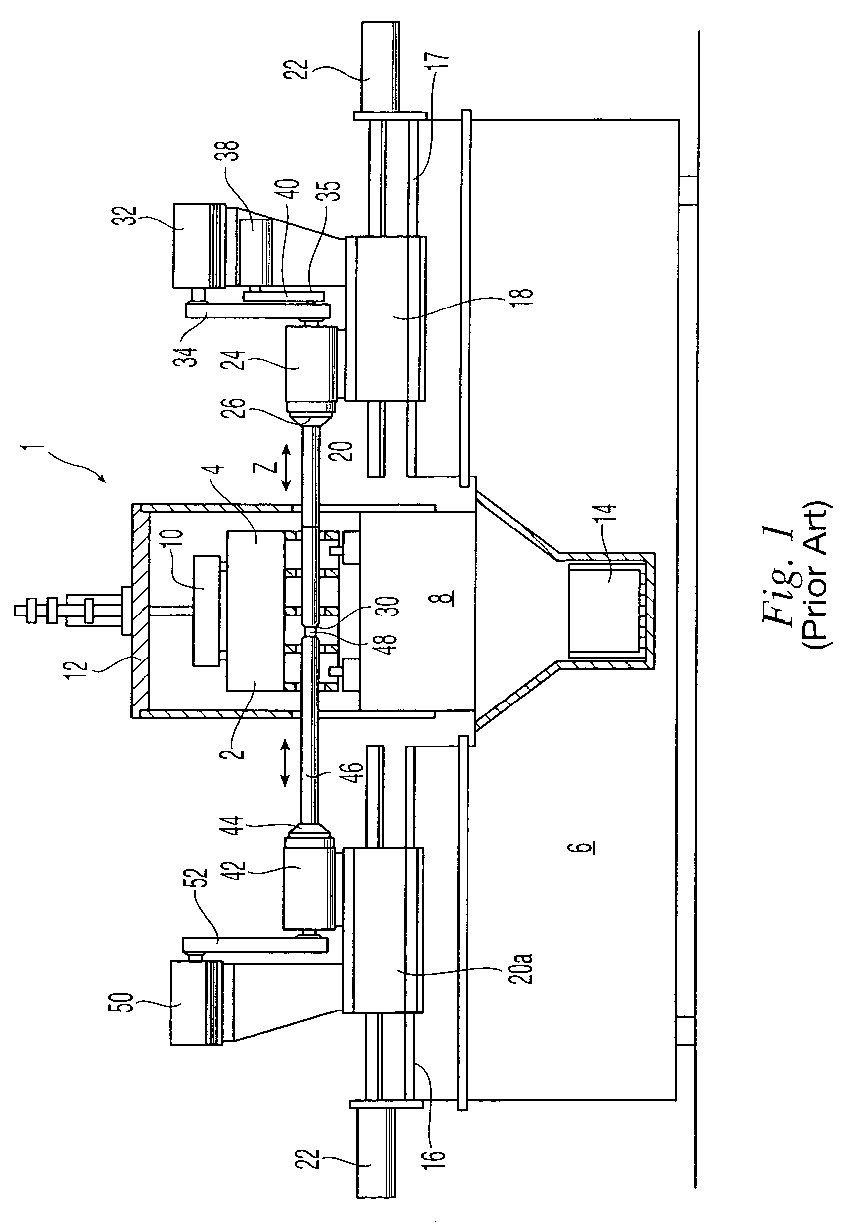
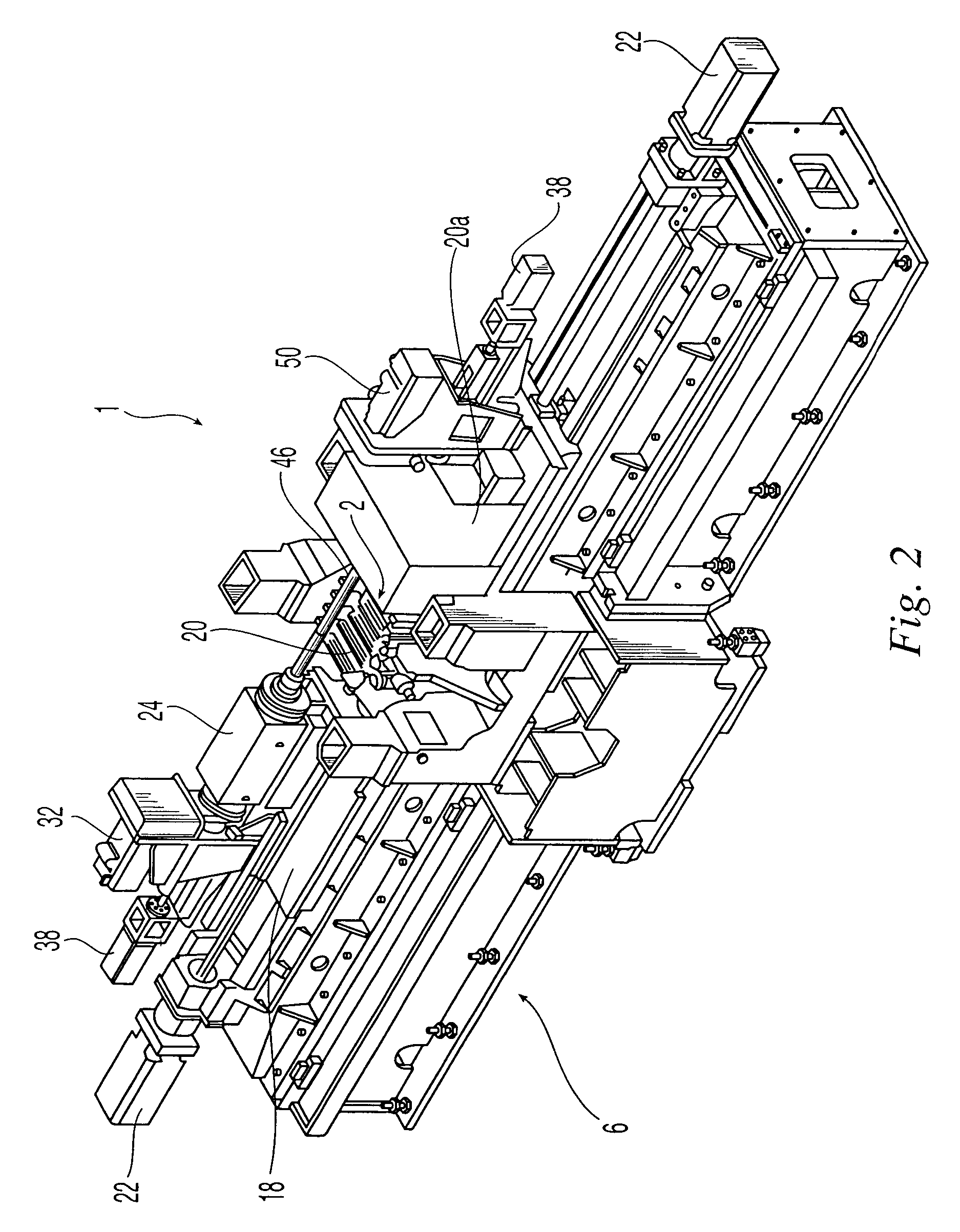
[0017]In FIG. 2, the parts corresponding to those already described with reference to FIG. 1 are indicated using the same reference number. The general layout of the machine in FIG. 2 is similar to that in FIG. 1. The main difference resides in the fact that, as is clearly visible in FIG. 2, both the boring bar 20 and the counter-bar 46, which at this point also becomes a boring bar, are equipped with at least one cutting bit indicated as P1, P2. In the illustrated example, each bar is in reality equipped with a pair of diametrically opposed bits P1 and P2. The bits of each pair are to work on the same seat each time.

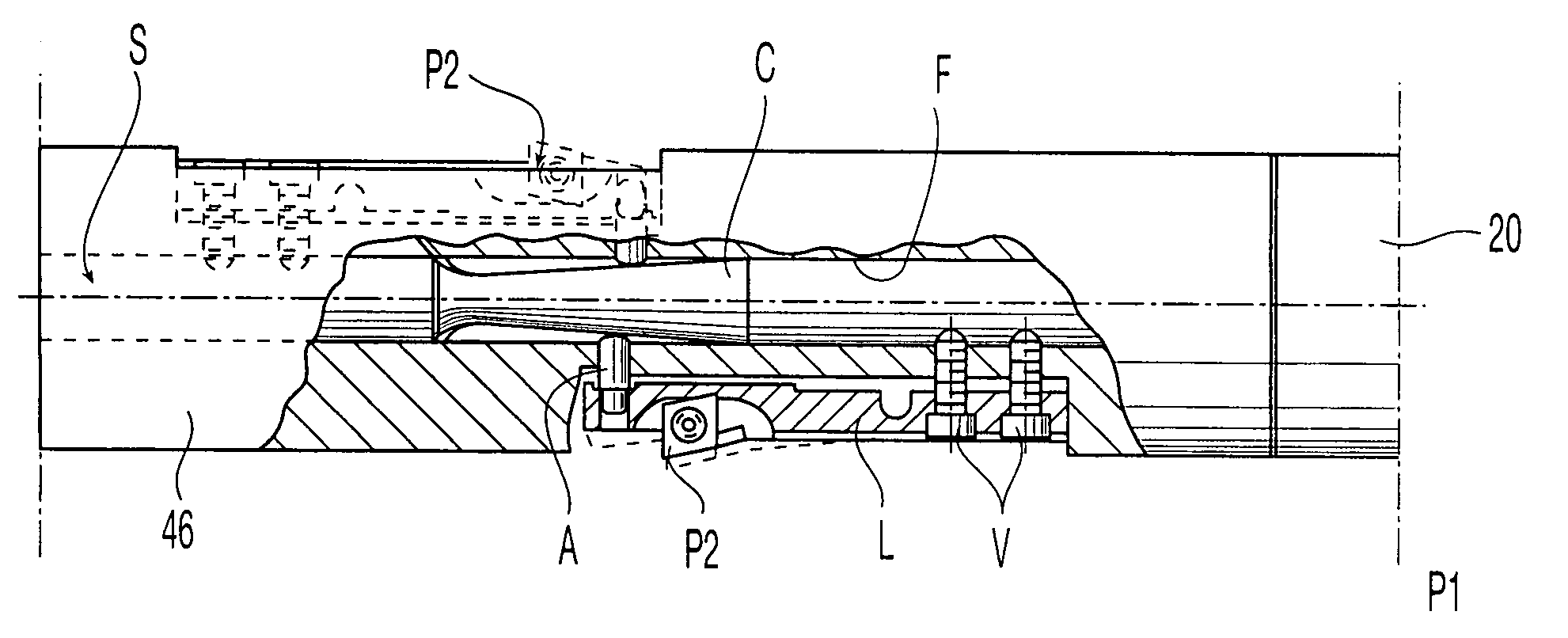
[0018]With reference to FIGS. 3–5, each of the cutting bits P1, P2 (FIGS. 4 and 5 refer to the case of the P2 bits) is carried by an elastically deformable blade L, fixed at one end to the respective bar by screws V. The two bars 20 and 46 are connected head-to-head in rotation using any type of coupling, such as a conical coupling (not visible in the drawings). Each bl...


PUM

PropertyMeasurementUnit
cycle timeaaaaaaaaaa
diameteraaaaaaaaaa

Abstract

A horizontal boring machine tool is described that includes a boring bar equipped with a cutting bit and a counter-bar coupled in head-to-head rotation with the boring bar. This counter-bar is also equipped with a cutting bit, or a series of cutting bits destined to operate simultaneously on the same cylindrical seat to be bored. Both the bit or bits arranged on the bar, and the bit or bits arranged on the counter-bar are radially adjustable via an automatic adjustment system.

Description

BACKGROUND OF THE INVENTION[0001]The present invention relates to horizontal boring machines for boring cylindrical surfaces having horizontal axes and axially separated from each other, such as the seats of an engine crankshaft in the crankcase of an internal combustion engine.[0002]In particular, the invention refers to horizontal boring machines of the type including a boring bar driven in rotation by a chuck and carrying at least one cutting bit, during means for driving rotation of said chuck, means for axially moving the group composed of the chuck and the associated driving means, a counter-bar coupled in rotation head-to-head with said boring bar and driven in rotation by a respective auxiliary chuck, driving means for driving rotation of the auxiliary chuck in synchronism with the rotation of the boring bar, and means for axially moving the group composed of said counter-bar and said driving means for driving rotation of the counter-bar in synchronism with the axial movemen...

Claims


Application Information

Patent Timeline
Patent Type & Authority Patents(United States)
IPC IPC(8): B23B41/12B23B29/02B23B29/034B23B39/00
CPCB23B29/02B23B29/034Y10T408/03Y10T82/12Y10T408/85843Y10S408/708
Inventor GIORDA, CLAUDIO
Owner COMAU SPA
Why Eureka
Try Eureka