Retractable lens barrel

a lens barrel and retraction technology, applied in the field of retraction lens barrels, can solve the problems of damage to the lens barrel, increase in production cost and dimensions of the lens barrel, etc., and achieve the effect of simple and low-cost structur

Inactive Publication Date: 2010-03-02
HOYA CORP
View PDF63 Cites 7 Cited by
  • Summary
  • Abstract
  • Description
  • Claims
  • Application Information

AI Technical Summary

Benefits of technology

[0006]The present invention provides a retractable lens barrel including at least one insertable optical element which can be selectively inserted into and removed from a photographic optical path, wherein the insertable optical element can be reliably removed from the photographic optical path on the photographing optical axis by a simple and low-cost structure when the lens barrel moves from a ready-to-photograph state to the retracted state thereof.
[0007]According to an aspect of the present invention, a lens barrel is provided, including at least one standard optical element used in a standard photographing operation and at least one insertable optical element which is selectively inserted into and removed from a photographing optical path, a photographic effect being produced by the insertable optical element when the insertable optical element is positioned in the photographic optical path. The lens barrel includes an accommodating driving device which moves the standard optical element and the insertable optical element rearward in an optical axis direction to change the lens barrel from a ready-to-photograph state to a retracted state; an insertable-optical-element drive mechanism which moves the insertable optical element between an inserted position, in which the insertable optical element is positioned on the optical axis on which the standard optical element is positioned, and a removed position, in which the insertable optical element is positioned off the optical axis, in accordance with an insertion signal and a remove signal for the insertable optical element, respectively, in the ready-to-photograph state of the lens barrel; and a forced removing device which forces the insertable optical element to move from the inserted position to the removed position independently of the insertable-optical-element drive mechanism when the lens barrel moves from the ready-to-photograph state to the retracted state by the accommodating driving device.
[0020]According to the present invention, even if a malfunction occurs in the operation of the drive mechanism for the insertable optical element, the insertable optical element can be reliably removed from the photographic optical path on the photographing optical axis by a simple and low-cost structure when the lens barrel moves from a ready-to-photograph state to the retracted state thereof.

Problems solved by technology

However, in the event of the insertable optical element not fully removing off the photographing optical axis due to some malfunction in the operation of the drive mechanism for the insertable optical element, there is a possibility of the insertable optical element interfering with other elements that are moved when the lens barrel is accommodated, which may cause damage to the lens barrel.
To prevent this from occurring, the lens barrel needs to be provided with a detector for detecting a removed state of the insertable optical element, which causes an increase in production cost and dimensions of the lens barrel.

Method used


Image

  • Retractable lens barrel
  • Retractable lens barrel
  • Retractable lens barrel

Examples


Embodiment Construction

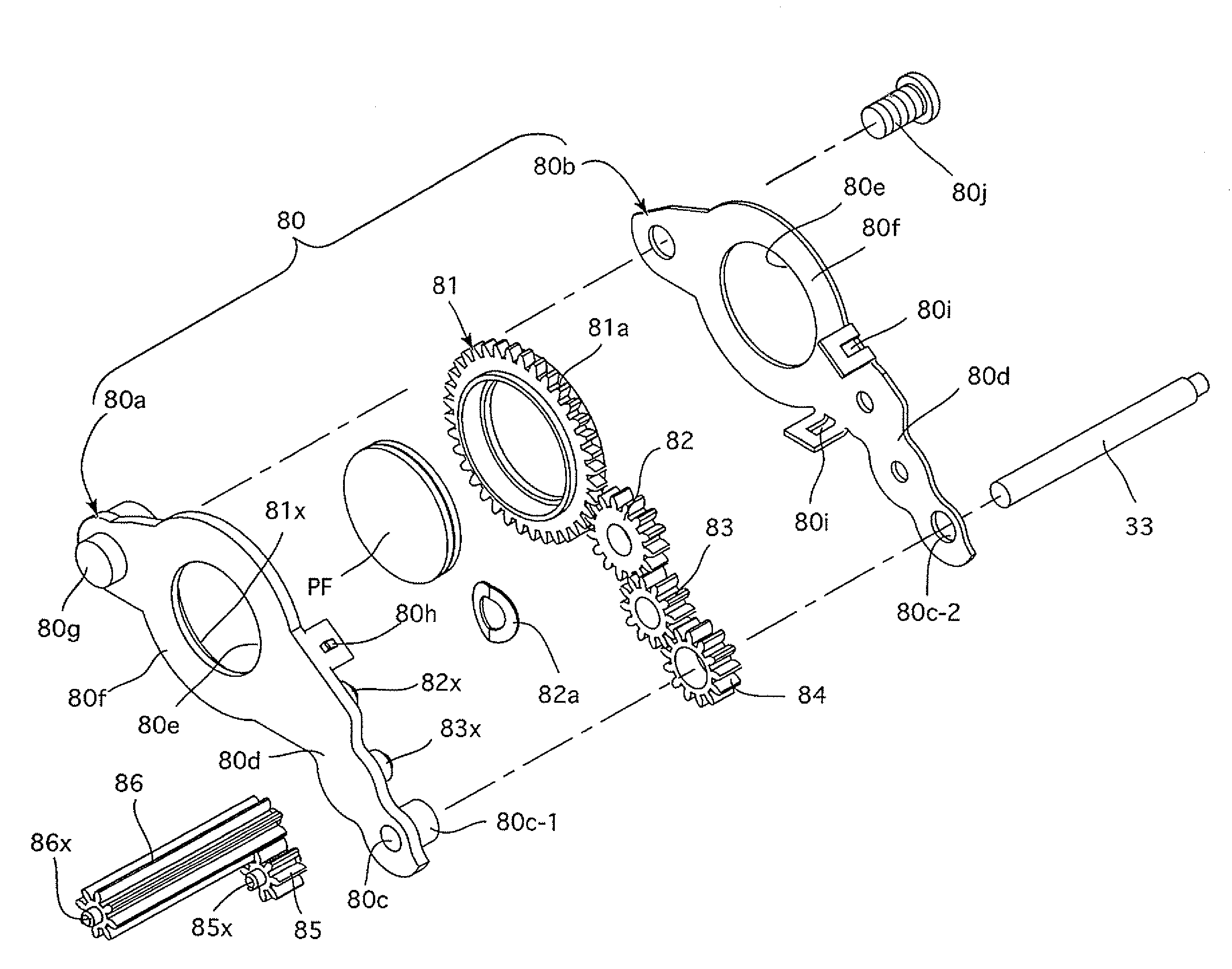
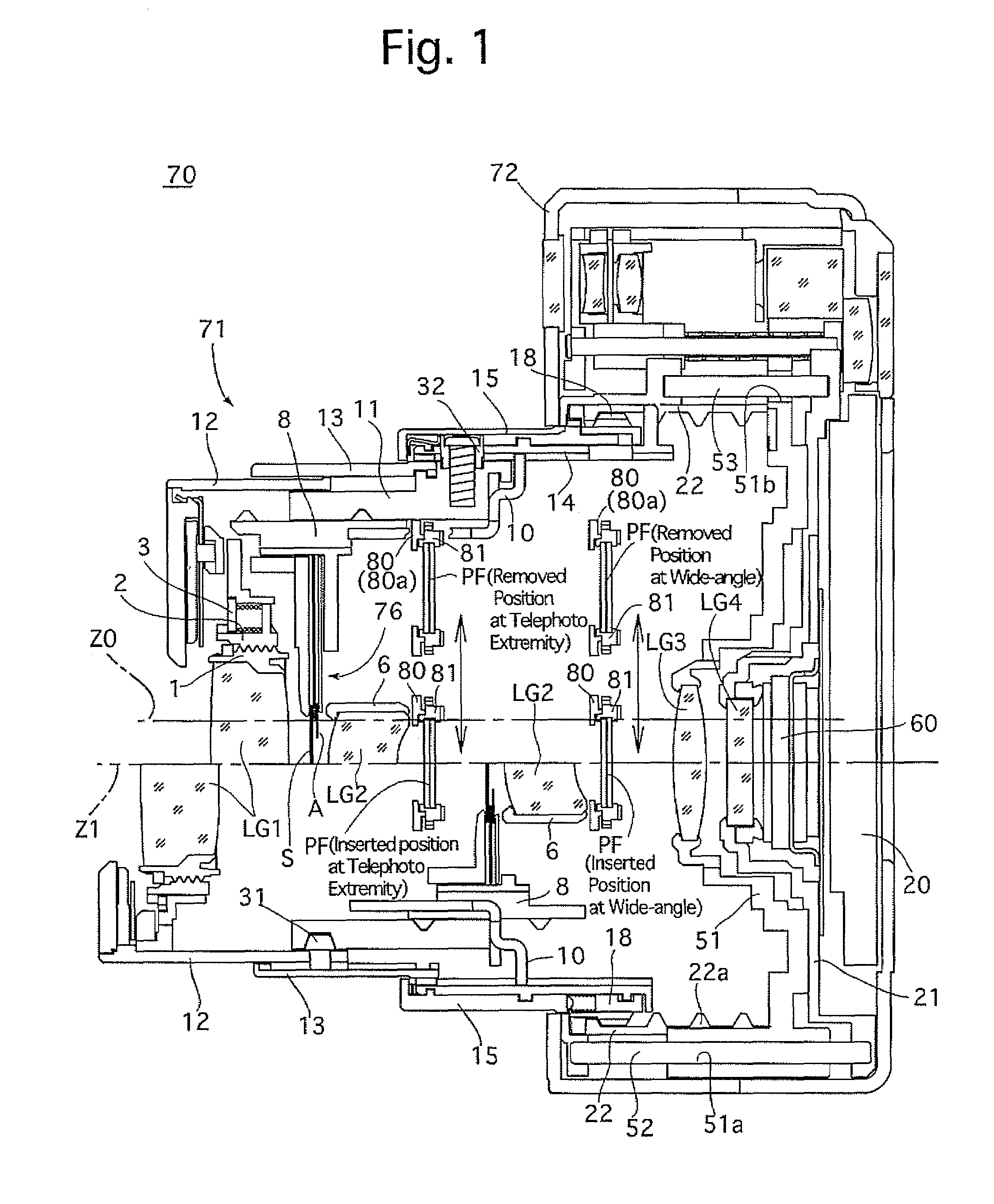
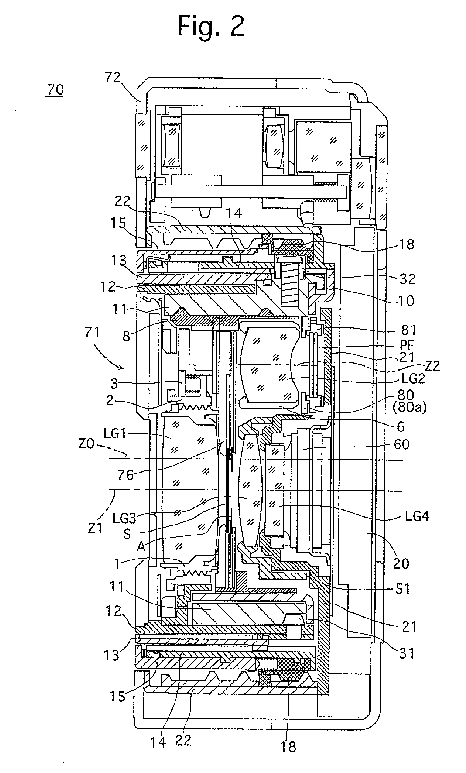
[0058]A zoom lens (zoom lens barrel) 71 of a digital camera 70, cross sections of which are shown in FIGS. 1 and 2, is changeable between a ready-to-photograph state shown in FIG. 1, in which the zoom lens 71 has advanced from a camera body 72 toward the object side, and an accommodated state (fully-retracted state) shown in FIG. 2, in which the zoom lens 71 is fully retracted into the camera body 72. In FIG. 1, a cross sectional view of an upper half portion of the zoom lens 71 above a photographing optical axis Z1 thereof shows a state of the zoom lens 71 at the telephoto extremity, while a cross sectional view of a lower half portion of the zoom lens 71 below the photographing optical axis Z1 shows a state of the zoom lens 71 at the wide-angle extremity. As shown in FIG. 8A, the zoom lens 71 is provided with a plurality of concentrically arranged ring members (cylindrical members): a second linear guide ring (second-lens-group linear guide ring) 10, a cam ring 11, a first externa...


PUM


Abstract

A lens barrel includes a standard optical element used in a standard photographing operation and an insertable optical element which is selectively inserted into and removed from a photographing optical path. The lens barrel includes an accommodating driving device which moves the standard optical element and the insertable optical element rearward in an optical axis direction from a ready-to-photograph state to a retracted state; an insertable-optical-element drive mechanism which moves the insertable optical element between an inserted position on the optical axis on which the standard optical element is positioned, and a removed position off the optical axis, in the ready-to-photograph state of the lens barrel; and a forced removing device which forces the insertable optical element to move from the inserted position to the removed position independently of the insertable-optical-element drive mechanism when the lens barrel moves from the ready-to-photograph state to the retracted state.

Description

BACKGROUND OF THE INVENTION[0001]1. Field of the Invention[0002]The present invention relates to a retractable lens barrel that reduces the length thereof when not in use, and more specifically, relates to such a retractable lens barrel including at least one insertable optical element which is inserted into and removed from a photographic optical path, wherein the insertable optical element is of a type that produces a specific photographic effect when positioned in the photographic optical path.[0003]2. Description of the Related Art[0004]In the case of providing a lens barrel with an insertable optical element such as an optical filter (e.g., a polarizing filter) or a wide-angle converter lens, wherein the insertable optical element is positioned on and off a photographing optical axis when the insertable optical element is in use and not in use, respectively, the operability of the insertable optical element in the case where the insertable optical element is inserted into and r...

Claims


Application Information

Patent Timeline
Patent Type & Authority Patents(United States)
IPC IPC(8): G03B17/00
CPCG03B17/00
Inventor NOMURA, HIROSHI
Owner HOYA CORP
Why Eureka
Try Eureka