Method for producing cavities for a turbomachine disk

a technology of turbomachine disks and turbine disks, which is applied in the field of aeronautics, can solve the problems of long production time of cavities, heavy investment, and high cost of consumables, and achieves the effects of long production time and high cost of machining the circumferential surface of the disk

Active Publication Date: 2016-12-22
SN DETUDE & DE CONSTR DE MOTEURS DAVIATION S N E C M A
View PDF2 Cites 5 Cited by
  • Summary
  • Abstract
  • Description
  • Claims
  • Application Information

AI Technical Summary

Benefits of technology

[0014]The invention offers a solution to the aforementioned problems, by proposing a method for producing sloping cavities of a turbomachine disk, applicable to two-tier disks, and which makes i

Problems solved by technology

However, the operations of machining the cavities (by broaching or milling), filleting and machining the circumferential surface of the disk require heavy investments

Method used


Image

  • Method for producing cavities for a turbomachine disk
  • Method for producing cavities for a turbomachine disk
  • Method for producing cavities for a turbomachine disk

Examples


Embodiment Construction

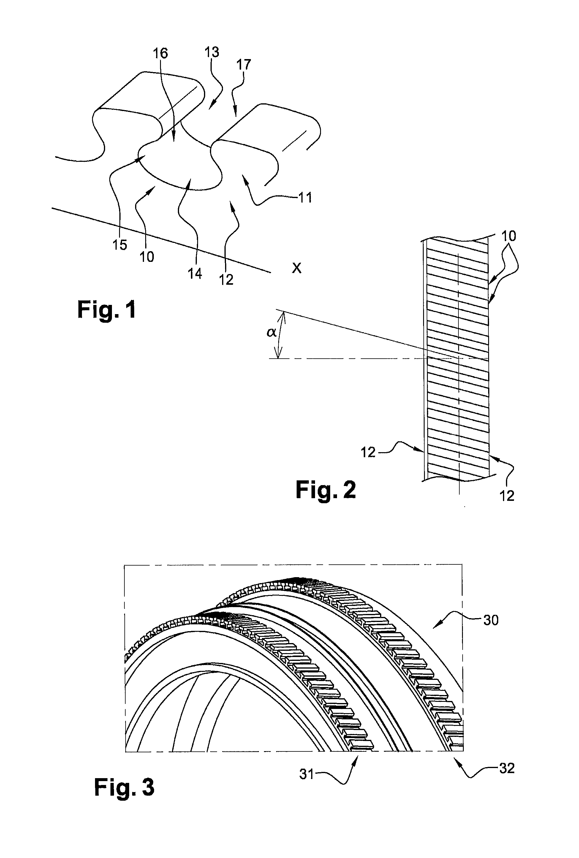
[0067]Unless stated otherwise, a same element appearing in the different figures has a single reference.

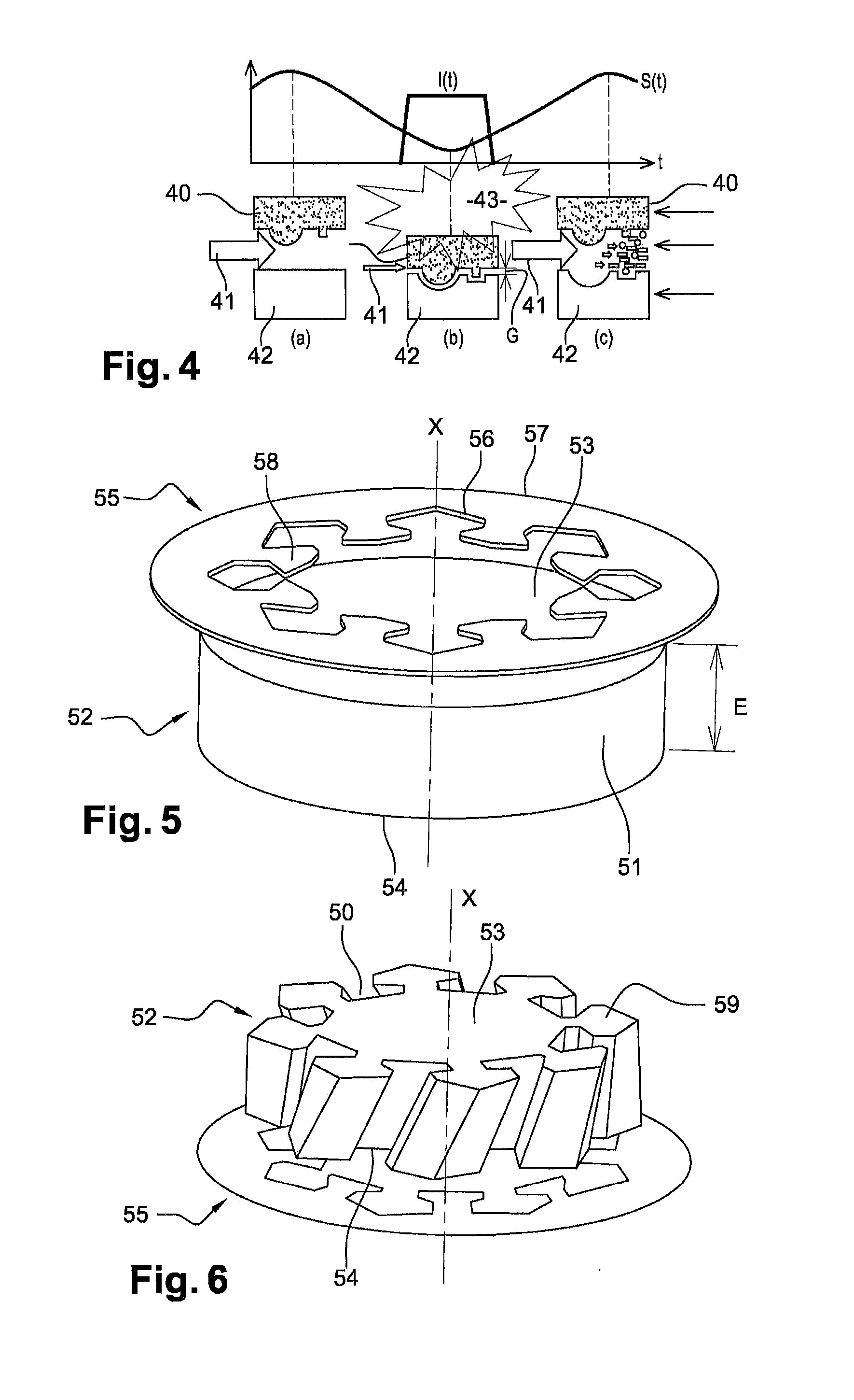
[0068]The method uses an electrochemical machining method, known as PECM (Pulsed Electrical Chemical Machining), known to those skilled in the art, the basic principles of which are given hereafter. PECM is a derivative of ECM (Electrical Chemical Machining), which is an electrochemical machining by anodic or oxidation-reduction dissolution of the material of a part. The machined shapes are obtained using a tool reproducing its inverted shape in the part by driving the tool into the part. In other words, the shapes of the tool and the part are complementary.

[0069]More precisely, with reference to FIG. 4, the PECM uses a pulsed current I(t) combined with an oscillatory movement S(t) of a tool 40. A pressurised electrolyte 41 circulates between the tool 40 and a part 42 to machine (steps (a), (b) and (c)). The shapes of the tool 40 and the part 42 have no relation with the invention...


PUM

PropertyMeasurementUnit
Speedaaaaaaaaaa
Shapeaaaaaaaaaa

Abstract

A method for producing cavities in a turbomachine disk, the cavities extending between first and second lateral surfaces of the disk, the method including positioning a ring facing the first surface, the ring including an inner periphery including protrusions complementary in shape to the cavities that are to be produced; circulating an electrolyte close to the protrusions on the ring; activating a first translational movement of the ring towards the second surface; activating a rotation of the disk; generating an electric current pulse in the electrolyte when the ring is substantially at the first surface, the pulse resulting in the ionic dissolution of the disk at the protrusions; reducing the speed of rotation to a first reduced speed, when the ring is substantially at the first surface, for a first period of time; and stopping the first translation of the ring when the ring is beyond the second surface.

Description

TECHNICAL FIELD OF THE INVENTION[0001]The invention relates to the general field of aeronautics. It relates to turbomachine turbine disks and more particularly methods for producing cavities for axially retaining blades borne by the disks.TECHNOLOGICAL BACKGROUND OF THE INVENTION[0002]A turbomachine turbine blade is composed of a disk and moving blades rotationally driven by the disk under the effect of a flow of fluid from upstream to downstream through the turbine. It may be noted that the terms “upstream” and “downstream” are to be considered with respect to a general direction of flow of fluids through the turbomachine, going from upstream to downstream.[0003]For the mounting of blades, the disk comprises on its circumferential surface a plurality of uniformly distributed teeth, protruding radially outwards from the disk and extending between two parallel lateral surfaces of the disk, said surfaces being orthogonal to the axis of rotation of the disk. The teeth are regularly spa...

Claims


Application Information

Patent Timeline
IPC IPC(8): B23H9/00F01D5/02B23H3/04
CPCB23H9/006B23H3/04F05D2230/10B23H2300/10F01D5/02B23H9/02B23H9/10B23H9/04
Inventor LECOMTE, JANVIERBUELYHA, JEAN-MICHELKRAFT, JURIGRUTZMACHER, ANDREAS
Owner SN DETUDE & DE CONSTR DE MOTEURS DAVIATION S N E C M A
Why Eureka
Try Eureka