Washing machine driving apparatus and washing machine including same

Active Publication Date: 2017-02-16
AMOTECH
View PDF0 Cites 9 Cited by
  • Summary
  • Abstract
  • Description
  • Claims
  • Application Information

AI Technical Summary

Benefits of technology

[0026]As described above, a washing machine driving apparatus according to the present invention may independently drive an inner rotor and an outer rotor, respectively, and may be provided with a planetary gear set in one of the inner rotor and the outer rotor, to thereby shift a rotation speed of any one of the inner rotor and the outer rotor to thus enable torque conversion.
[0027]In addition, a washing machine driving apparatus according to the present invention is configured to include a protector protecting a rotor provided with a stator to thus protect the rotating rotor, to thereby prevent interference between the rotor and other parts, to thus mount the oth

Problems solved by technology

However, the conventional washing machine needs the planetary gear set and the clutch in order to selectively rotate the pulsator and the inner tub, to accordingly cause the configuration of the conventional washing machine to be complicated and the production cost thereof to increase.
Otherwise, since the height of the inner tub should be reduced in an identical height of the washing machine, there is a problem that a washing capacity is reduced.
As

Method used


Image

  • Washing machine driving apparatus and washing machine including same
  • Washing machine driving apparatus and washing machine including same
  • Washing machine driving apparatus and washing machine including same

Examples


Example

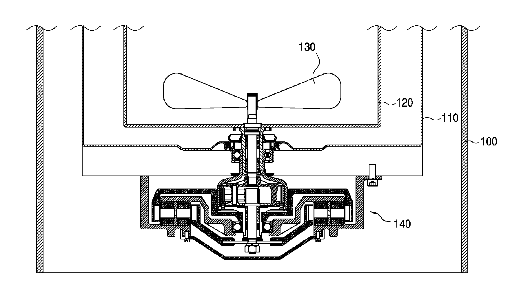
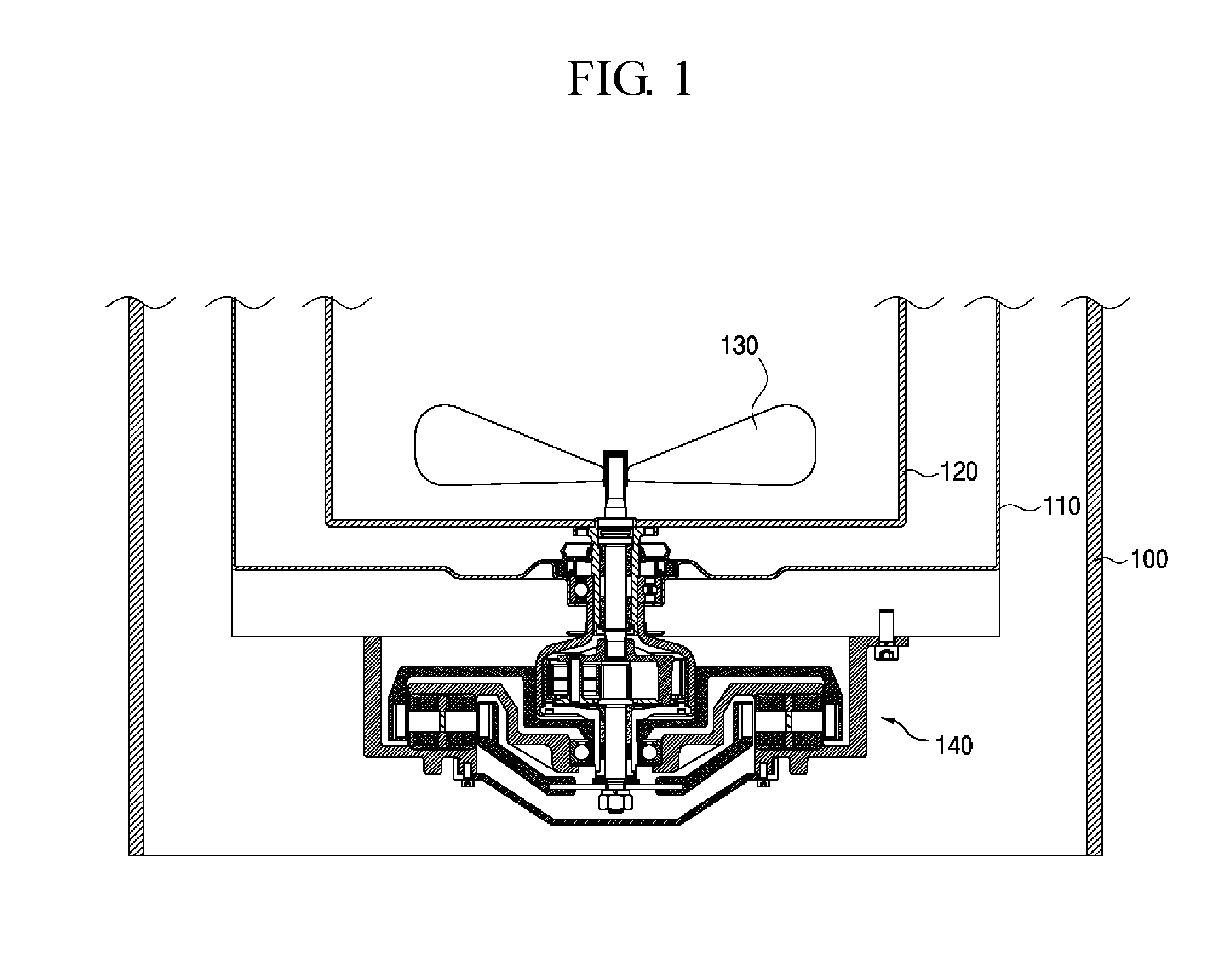
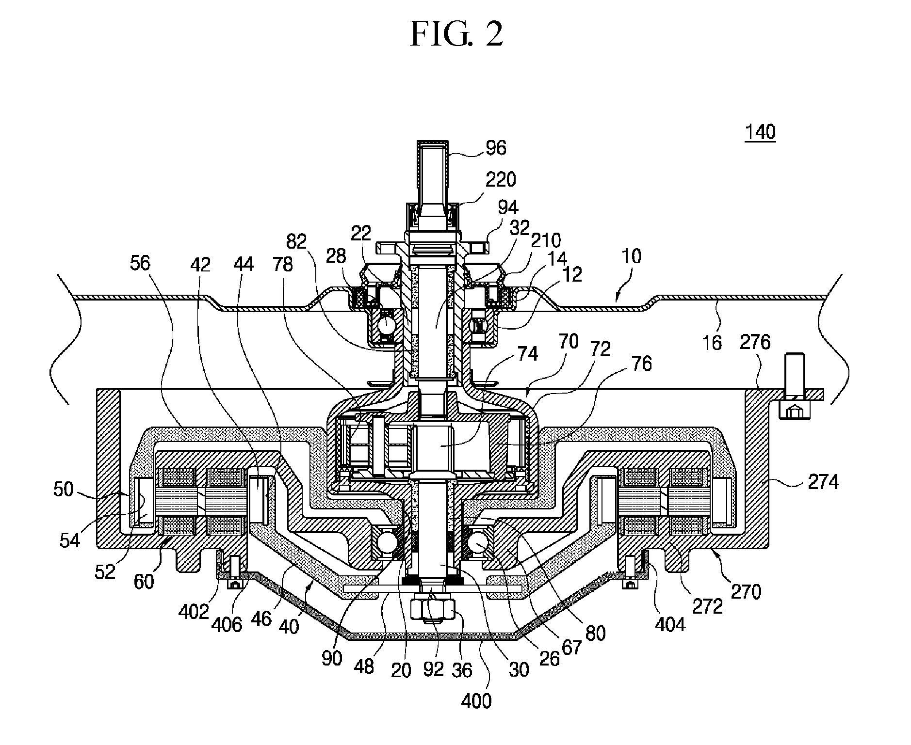
[0038]FIG. 1 is a cross-sectional view of a washing machine according to an embodiment of the present invention, and FIG. 2 is a cross-sectional view of a washing machine driving apparatus according to a first embodiment of the present invention.

[0039]Referring to FIG. 1, a washing machine according to an embodiment of the present invention includes: a case 100 forming an outer appearance; an outer tub 110 which is disposed in an inside of the case 100 and accommodating washing water; a washing tub 120 which is rotatably disposed inside the outer tub 110 to perform washing and dehydrating; a pulsator 130 which is rotatably disposed inside the washing tub 120 to form washing water flows; and a washing machine driving apparatus 140 which is mounted under the washing tub 120 and the outer tub 120, to provide a driving force necessary for a washing stroke, a rinsing stroke, a detangle stroke, and a dehydrating stroke, for the washing tub 120 and the pulsator 130, simultaneously or selec...

Example

[0086]FIG. 4 shows a washing machine driving apparatus according to a second embodiment, in which a stator support has a structure different from that of the first embodiment.

[0087]The stator support 500 according to the second embodiment includes: a core fixing portion 502 in which a stator core 62 is mounted; a bearing fixing portion 504 that extends inwardly from the core fixing portion 502 and holds a first bearing 26; a cover portion 506 extending outwardly from the core fixing portion 502 and formed in a cylindrical shape thereby protecting the outer rotor 50; an outer tub fixing portion 508 extending outwardly from the cover portion 506 and fixed to the outer tub 110; and a protective fence which extends from a lower surface of the core fixing portion 502.

[0088]The protective fence according to the second embodiment includes a protector 510 that is formed in a cylindrical shape extending integrally from the core fixing portion 502 of the stator support 500, or that is arrange...


PUM


Abstract

A washing machine driving apparatus comprises: a drive motor of a double rotor-double stator structure where the drive motor comprises an inner rotor and an outer rotor controllable independently by a double stator, and optionally generating inner rotor output and outer rotor output; a first inner shaft transferring the inner rotor output as a first input; a first outer shaft rotatably coupled to an outer periphery of the first inner shaft, and transferring the outer rotor output as a second input; a planetary gear unit where a gear ratio of a transmission output generated from a carrier is controlled by the second input applied to a ring gear through the first outer shaft, when the first input is applied to a sun gear through the first inner shaft; and a protection unit protecting the inner rotor where an outer peripheral portion of protection unit is supported by the double stator.

Description

TECHNICAL FIELD[0001]The present invention relates to a washing machine driving apparatus that may drive an inner rotor and an outer rotor independently, and a washing machine having the same.BACKGROUND ART[0002]As disclosed in Korean Patent Registration Publication No. 10-0548310 on Jan. 24, 2006, a conventional washing machine includes: an outer case forming an outer shape; an outer tub which is supported on an inside of the outer case and receives wash water therein; an inner tub which is rotatably accommodated in an inside of the outer tub and is used for both washing and dehydrating; a pulsator which is mounted relatively rotatably in an inside of the inner tub, to thus form a washing water flow; a drive motor for generating a driving force for rotating the inner tub and the pulsator; an inner tub rotating shaft which receives the driving force of the drive motor thereby rotating the inner tub; a pulsator rotating shaft which receives the driving force of the drive motor thereb...

Claims


Application Information

Patent Timeline
IPC IPC(8): D06F37/30D06F37/20D06F37/26H02K7/00D06F23/04H02K7/116H02K16/00D06F37/40D06F37/12
CPCD06F37/304D06F37/40D06F37/206D06F37/26H02K7/003D06F23/04H02K7/116H02K16/00D06F37/12H02K2213/12D06F37/30D06F37/20H02K7/10H02K16/02
Inventor KIM, BYUNG SOOKO, HYUNG HWANKIM, HAK ROKLEE, SE KI
Owner AMOTECH
Why Eureka
Try Eureka