Fuel rail for an internal combustion engine

a fuel rail and internal combustion engine technology, applied in the direction of machines/engines, fuel injection apparatus, feed systems, etc., can solve the problems of reduced engine efficiency, reduced fuel economy, and fuel pulsation in the fuel system of the sidi engine, so as to improve overall fuel economy and engine efficiency, the effect of reducing pressure variations

Inactive Publication Date: 2017-02-23
HITACHI ASTEMO AMERICAS INC
View PDF8 Cites 3 Cited by
  • Summary
  • Abstract
  • Description
  • Claims
  • Application Information

AI Technical Summary

Benefits of technology

[0012]The present invention provides a fuel rail for a liquid fuel internal combustion engine having multiple fuel injectors which minimizes the pressure variations within the fuel rail between the different fuel injectors.
[0017]The position of the orifice or orifices formed through the tube and thus fluidly connecting the inlet chamber with the outlet chamber is preferably empirically determined to minimize the pressure variations caused by the pump pulsations between the injector ports. By thus equalizing, or nearly equalizing the pressure within the annular outlet chamber at each fuel injector port, the quantity of fuel injected by each fuel injector will be substantially the same. In doing so, the overall fuel economy and engine efficiency is improved.

Problems solved by technology

The fuel pulsations in the fuel system for the SIDI engine can create substantial noise in the fuel system, especially at low engine speeds.
Such an uneven quantity of fuel injection into the different cylinders for the SIDI engine results in decreased engine efficiency and reduced fuel economy.
While there have been many previously known devices directed to reducing pressure pulsations within the fuel rail in an attempt to reduce noise from the fuel system, none of these prior art devices have addressed the issue of non-uniform fuel injection into the engine combustion chambers by the different fuel injectors.

Method used


Image

  • Fuel rail for an internal combustion engine
  • Fuel rail for an internal combustion engine
  • Fuel rail for an internal combustion engine

Examples


Embodiment Construction

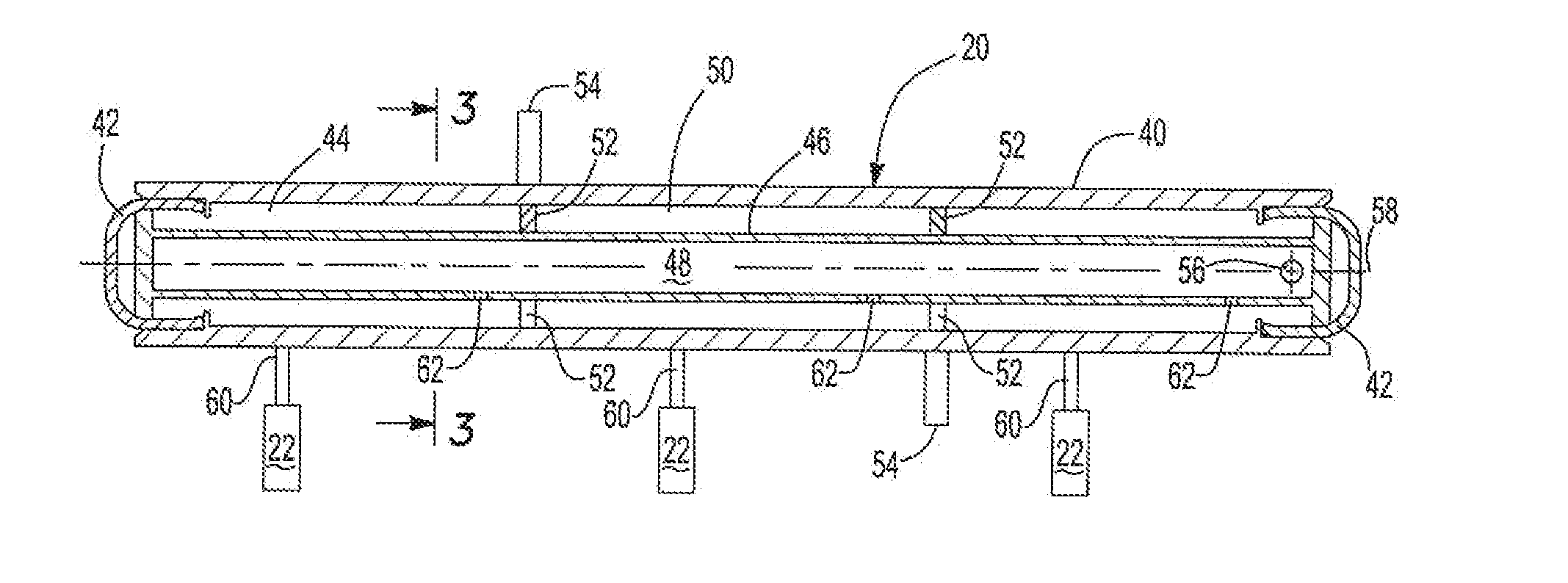
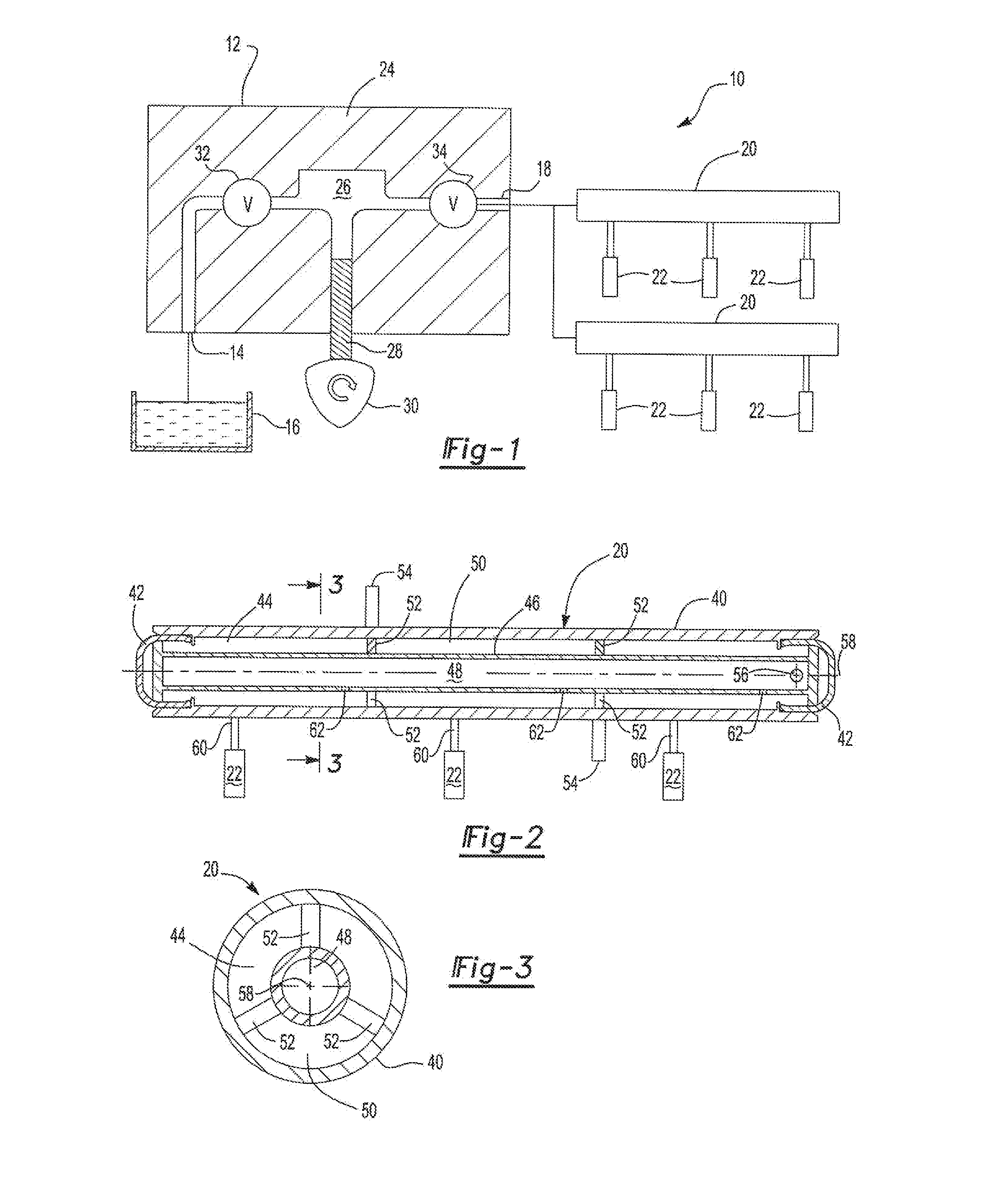
[0028]With reference first to FIG. 1, a fuel system 10 for a liquid fuel internal combustion engine, such as a spark ignition direct injection engine, is illustrated. The fuel system 10 includes a fuel pump 12 (illustrated diagrammatically) having its inlet 14 fluidly connected to a fuel source 16, such as the fuel tank.. An outlet 18 from the fuel pump 12 is fluidly connected to one or more elongated fuel rails 20. Each fuel rail 20, furthermore, supplies fuel to two or more fuel injectors 22.

[0029]The fuel pump 12 is of conventional construction, such as illustrated in FIG. 9, and includes a housing 24 defining a pump chamber 26. A plunger 28 is reciprocally mounted within the pump chamber 26 and is reciprocally driven by a cam 30.

[0030]The pump inlet 14 is connected through an inlet valve 32, which may be solenoid actuated, to the pump chamber 26. A one-way outlet check valve 34 is fluidly connected in series between the pump chamber 26 and the fuel rails 20.

[0031]In the well-kno...


PUM


Abstract

A fuel rail for a direct injection engine. The fuel rail includes an elongated tubular housing which defines an elongated main chamber. An elongated tube is disposed in the main chamber of the housing and defines an inlet chamber inside of the tube and an annular outlet chamber between the housing and the tube. The tube has a fuel inlet open to its inlet chamber and adapted for connection with a fuel pump. At least two orifices are formed through the tube which fluidly connects the inlet chamber with the outlet chamber. The orifices are positioned and sized to minimize fuel pressure gradients in the fuel rail caused by fuel injection by the fuel injectors.

Description

BACKGROUND OF THE INVENTION[0001]I. Field of the Invention[0002]The present invention relates to a fuel rail for an internal combustion engine.[0003]II. Description of Related Art[0004]The use of SIDI (spark ignition by direct injection) internal combustion engines in the automotive industry has enjoyed increased popularity. The increased popularity and use of SIDI engines in the automotive industry results primarily from better fuel economy and more efficient operation of the engine.[0005]As shown in FIG 8, in a conventional fuel system 100 for a SIDI engine, a fuel pump 102 has its inlet 104 connected to a fuel source 106, usually the fuel tank, and its outlet 108 connected to one or more fuel rails 110 that are disposed adjacent the fuel combustion chambers of the engine. A fuel injector 112 is associated with each combustion chamber for the engine and these fuel injectors 112 are fluidly connected to the fuel rail 110. Thus, in the normal operation, the pump 102 supplies fuel to...

Claims


Application Information

Patent Timeline
Patent Type & Authority Applications(United States)
IPC IPC(8): F02M63/02F02M59/10
CPCF02M59/102F02M63/0265F02M55/025F02M69/465F02M2200/315
Inventor MCCUNE, DONALD J.AVIREDDI, PRASHANTH
Owner HITACHI ASTEMO AMERICAS INC
Why Eureka
Try Eureka