Method of monitoring subsurface concrete structures

Active Publication Date: 2017-03-09
KVAERNER CEMENTATION FOUND LTD +2
View PDF6 Cites 15 Cited by
  • Summary
  • Abstract
  • Description
  • Claims
  • Application Information

AI Technical Summary

Benefits of technology

[0015]The disclosure allows for real-time temperature monitoring of the structure during hydration of the concrete, thereby providing a mechanism for identifying potential anomalies and defects (e.g. due to the presence of voids, fissures or non-homogeneous concentrations within the structure) during formation and before the structure is completed.
[0016]It is highly desirable to ensure that a uniform concrete structure has been formed and that there are no anomalies which will cause the structure to be weak. Concrete defects could be present due to a congested reinforcement, which is difficult to detect. By using methods according to e

Problems solved by technology

A problem arises when the built structure is inaccessible, e.g. if the structure is at a subsurface location.
However, in the case

Method used


Image

  • Method of monitoring subsurface concrete structures
  • Method of monitoring subsurface concrete structures
  • Method of monitoring subsurface concrete structures

Examples


Example

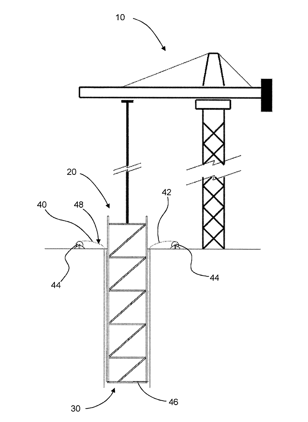
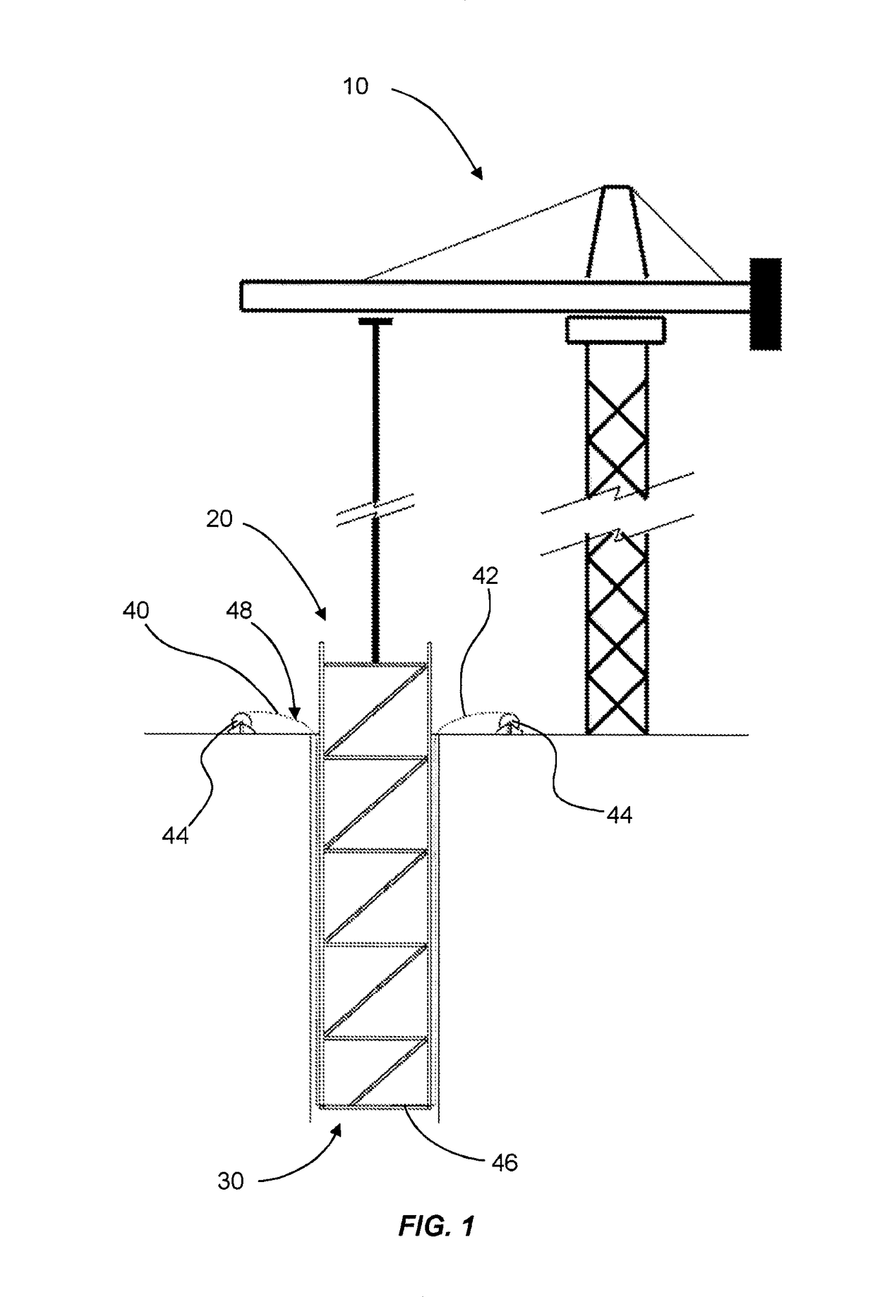
[0038]Referring firstly to FIG. 1, a crane or other suitable lifting device 10 is shown lowering a reinforcement or framework assembly 20 into a borehole or cavity 30 in the ground, for the purpose of creating a subsurface concrete structure.

[0039]Once the assembly 20 has been positioned at the desired location, concrete (not shown) is applied to fill the borehole or cavity 30, thereby surrounding the assembly 20.

[0040]In an alternative method, the concrete may be placed first, with the assembly 20 then placed into the wet concrete.

[0041]As will be understood, the concrete will undergo a period of hydration, during which the concrete will harden to create a subsurface concrete structure having integral reinforcement or framework.

[0042]The reinforcement or framework assembly 20 (hereinafter referred to as ‘the assembly’) is configured to define a substructure of the subsurface concrete structure to be created. As such, the assembly 20 may typically be constructed as a cage or frame, ...


PUM


Abstract

Fibre optic sensors are used to monitor the integrity of a subsurface concrete structure such as a pile or diaphragm wall. A fibre optic sensor array (48) is attached to a reinforcement or framework assembly (20) for the subsurface concrete structure. Concrete is applied to surround the reinforcement or framework assembly (20) and fibre optic sensor array (48). The fibre optic sensor array (48) is then used to collect temperature data during hydration of the subsurface concrete structure. The temperature data is monitored in real time to determine differentials across the structure, indicative of a problem within the structure.

Description

BACKGROUND[0001]There is a need to minimise failures within the built environment. In recent years, this has been driven not only by safety considerations, but also by a need to optimise the use of limited natural resources.[0002]As such, it is necessary to monitor built structures, in order to identify potential failures. A problem arises when the built structure is inaccessible, e.g. if the structure is at a subsurface location.[0003]Subsurface concrete structures are generally made by pouring fresh concrete into a cavity (such as an underground borehole, or a shuttered structure to contain the concrete). They require non-visual assessment after curing to ensure that the poured concrete is present in the designed quantity at all points in the structure and that there are no voids, bulges or significant anomalies in the concrete.[0004]In some cases, strain gauges are used to facilitate non-visual assessment of subsurface structures after curing. The non-visual assessment of subsurf...

Claims


Application Information

Patent Timeline
IPC IPC(8): E02D33/00E02D5/18E02D15/04E02D5/22G01K11/32G01V9/00
CPCE02D33/00G01K11/32G01V9/005G01N33/383E02D5/22E02D5/18E02D15/04E21B33/14G01N21/431E21B47/005E21B47/135
Inventor BELL, ANDREWOUYANG, YUESOGA, KENICHINICHOLSON, DUNCAN
Owner KVAERNER CEMENTATION FOUND LTD
Why Eureka
Try Eureka